
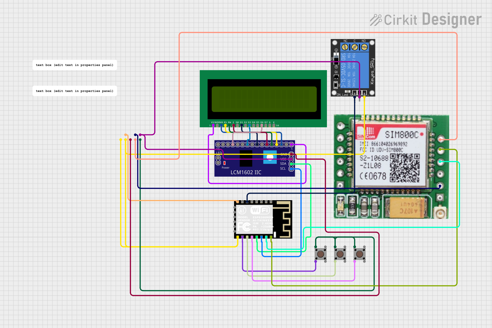
Circuit Documentation
Summary
This circuit involves multiple pushbuttons, an LCD display, a GSM module, a WiFi module, a power supply, and a relay. The circuit is designed to interact with an LCD display, control a relay, and communicate via GSM and WiFi. The pushbuttons are used for user input, and the microcontroller code handles the logic for displaying information on the LCD, controlling the relay, and managing communication protocols.
Component List
Pushbutton
- Description: A simple pushbutton used for user input.
- Pins: Pin 1 (in), Pin 2 (in), Pin 3 (out), Pin 4 (out)
16X2 LCD
- Description: A 16x2 character LCD display.
- Pins: VSS, VDD, V0, RS, RW, E, D0, D1, D2, D3, D4, D5, D6, D7, A, K
LCM1602 IIC
- Description: An I2C interface for the 16x2 LCD display.
- Pins: GND, VCC, SDA, SCL, D0, D1, D2, D3, D4, D5, D6, D7, RS, RW, E, VSS, VDD, V0, LED_A, LED_B
SIM800c GSM Module
- Description: A GSM module for cellular communication.
- Pins: SPK-, SPK+, MIC-, MIC+, DTR, RING, GND, TXD, RXD, LINK GND, ANT, VCC(3.7 - 4.2)
ESP8266 ESP-12F WiFi Module
- Description: A WiFi module for wireless communication.
- Pins: GND, GPIO15, GPIO2, GPIO0, GPIO4, GPIO5, RXD0, TXD0, RST, ADC0, EN, GPIO16, GPIO14, GPIO12, GPIO13, VCC, SCLK, MOSI, GPIO10, GPIO9, MISO, CS0
Mtiny Power
- Description: A power supply module providing 3.3V, 5V, and VIN.
- Pins: 3V3, 5V, GND, VIN
1-Channel Relay (5V 10A)
- Description: A relay module for switching high-power devices.
- Pins: NC, signal, C, power, NO, ground
Comment
- Description: Placeholder for comments or notes in the circuit.
- Pins: None
Wiring Details
Pushbutton
- Pin 1 (in): Connected to GND of Mtiny Power
- Pin 2 (in): Connected to GPIO15 of ESP8266 ESP-12F WiFi Module
Pushbutton
- Pin 1 (in): Connected to GND of Mtiny Power
- Pin 2 (in): Connected to GPIO0 of ESP8266 ESP-12F WiFi Module
Pushbutton
- Pin 1 (in): Connected to GND of Mtiny Power
- Pin 2 (in): Connected to GPIO2 of ESP8266 ESP-12F WiFi Module
16X2 LCD
- VSS: Connected to VSS of LCM1602 IIC
- V0: Connected to V0 of LCM1602 IIC
- RS: Connected to RS of LCM1602 IIC
- RW: Connected to RW of LCM1602 IIC
- E: Connected to E of LCM1602 IIC
- D1: Connected to D1 of LCM1602 IIC
- D3: Connected to D3 of LCM1602 IIC
- D6: Connected to D6 of LCM1602 IIC
LCM1602 IIC
- GND: Connected to GND of Mtiny Power
- VCC: Connected to 5V of Mtiny Power and power of 1-Channel Relay
- SDA: Connected to GPIO4 of ESP8266 ESP-12F WiFi Module
- SCL: Connected to GPIO5 of ESP8266 ESP-12F WiFi Module
SIM800c GSM Module
- GND: Connected to GND of Mtiny Power
- TXD: Connected to TXD0 of ESP8266 ESP-12F WiFi Module
- RXD: Connected to RXD0 of ESP8266 ESP-12F WiFi Module
- VCC(3.7 - 4.2): Connected to 5V of Mtiny Power
ESP8266 ESP-12F WiFi Module
- GND: Connected to GND of Mtiny Power and ground of 1-Channel Relay
- GPIO12: Connected to signal of 1-Channel Relay
- VCC: Connected to 5V of Mtiny Power
Mtiny Power
- GND: Connected to GND of Pushbuttons, LCM1602 IIC, SIM800c GSM Module, ESP8266 ESP-12F WiFi Module, and 1-Channel Relay
- 5V: Connected to VCC of LCM1602 IIC, SIM800c GSM Module, and ESP8266 ESP-12F WiFi Module
1-Channel Relay (5V 10A)
- power: Connected to VCC of LCM1602 IIC
- ground: Connected to GND of Mtiny Power
- signal: Connected to GPIO12 of ESP8266 ESP-12F WiFi Module
Code Documentation
sketch.ino
#include <LiquidCrystal_I2C.h>
#include <EEPROM.h>
#include <Wire.h>
#include <SoftwareSerial.h>
#include <PubSubClient.h>

// Настройка LCD-дисплея
LiquidCrystal_I2C lcd(0x27, 16, 2);

// Настройка кнопок
const byte buttons[] = {21, 22, 23}; // Обновите с правильными номерами пинов
const byte nrButtons = sizeof(buttons) / sizeof(buttons[0]);
const int menusize = 13;
const String menu[] = {
  "Menu",
  "Menu>Rele",
  "Menu>Rele>Off",
  "Menu>Rele>On",
  "Menu>Info",
  "Menu>Info>Lamp status",
  "Menu>Setup",
  "Menu>Setup>Lamp resurs setup",
  "Menu>Setup>Reset lamp",
  "Menu>Setup>Reset lamp>off",
  "Menu>Setup>Reset lamp>on",
  "Menu>Setup>Room volume",
  "Menu>Setup>Room volume>Set",
};

const int roomVolumes[] = {10, 15, 20, 30};
const int numRoomVolumes = sizeof(roomVolumes) / sizeof(roomVolumes[0]);
int currentRoomVolumeIndex = 0;

int currentPos = 0, currentPosParent = 0, possiblePosScroll = 0;
int possiblePos[20], possiblePosCount = 0;
int brightness = 0, resurs_lamp = 9000, last_time_on_resurs_lamp = 0, resurs_lamp_old = 0;
int LCDtoggle = 0, fadeAmount = 5, releMode = 0;
unsigned long timer = millis() / 10, relayOnTime = 0;
unsigned long relayOffTime = 900000; // Время отключения реле в миллисекундах (по умолчанию 15 минут)

// Настройка GSM-модуля и MQTT
SoftwareSerial sim800(10, 11); // RX, TX
const char* mqtt_server = "your_mqtt_broker_address";
const char* mqtt_user = "your_mqtt_username";
const char* mqtt_password = "your_mqtt_password";
const char* mqtt_topic = "your_mqtt_topic";

WiFiClient espClient;
PubSubClient client(espClient);

void setup() {
  Serial.begin(9600);
  sim800.begin(9600);
  lcd.init();
  lcd.begin(16, 2);
  lcd.clear();

  for (byte t = 0; t < nrButtons; t++) {
    pinMode(buttons[t], INPUT_PULLUP);
  }

  pinMode(9, OUTPUT);

  lcd.setCursor(0, 0);
  lcd.print("HELLO");
  delay(1000);
  updateMenu();
  EEPROM.get(1, last_time_on_resurs_lamp);
  EEPROM.get(2, resurs_lamp);
  EEPROM.get(3, currentRoomVolumeIndex);
  calculateRelayOffTime();

  // Настройка MQTT
  client.setServer(mqtt_server, 1883);
  client.setCallback(callback);
}

void loop() {
  if (!client.connected()) {
    reconnect();
  }
  client.loop();

  switch (releMode) {
    case 0:
      analogWrite(9, 0);
      break;