
ESP8266 NodeMCU Wi-Fi Controlled Smart Parking System with Reed Switches and LED Indicators
View and Edit Project In Cirkit Designer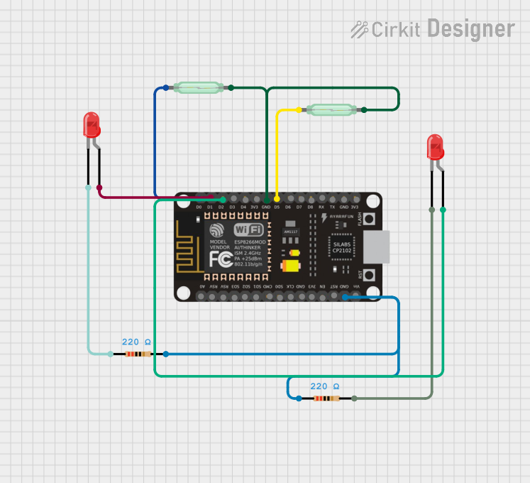
Circuit Documentation
Summary
This circuit is designed to monitor parking slots using reed switches and LEDs, controlled by an ESP8266 NodeMCU microcontroller. The circuit detects the presence of cars in parking slots and updates the status on a Firebase database. LEDs are used to indicate the occupancy status of the parking slots.
Component List
ESP8266 NodeMCU
- Description: A low-cost Wi-Fi microcontroller with GPIO pins.
- Pins: D0, D1, D2, D3, D4, 3V3, GND, D5, D6, D7, D8, RX, TX, A0, RSV, SD3, SD2, SD1, CMD, SD0, CLK, EN, RST, VIN
Reed Switch (1)
- Description: A magnetic switch used to detect the presence of a car.
- Pins: pin 1, pin 2
Reed Switch (2)
- Description: A magnetic switch used to detect the presence of a car.
- Pins: pin 1, pin 2
LED: Two Pin (red) (1)
- Description: A red LED used to indicate the occupancy status of a parking slot.
- Pins: cathode, anode
LED: Two Pin (red) (2)
- Description: A red LED used to indicate the occupancy status of a parking slot.
- Pins: cathode, anode
Resistor (1)
- Description: A resistor used to limit the current through the LED.
- Pins: pin1, pin2
- Properties: 220 Ohms
Resistor (2)
- Description: A resistor used to limit the current through the LED.
- Pins: pin1, pin2
- Properties: 220 Ohms
Wiring Details
ESP8266 NodeMCU
- D0 is connected to pin 1 of Reed Switch (2).
- D1 is connected to anode of LED: Two Pin (red) (2).
- D2 is connected to anode of LED: Two Pin (red) (1).
- D5 is connected to pin 1 of Reed Switch (1).
- GND is connected to:
- pin 2 of Reed Switch (1)
- pin 2 of Reed Switch (2)
- pin1 of Resistor (2)
- pin1 of Resistor (1)
Reed Switch (1)
- pin 1 is connected to D5 of ESP8266 NodeMCU.
- pin 2 is connected to GND of ESP8266 NodeMCU.
Reed Switch (2)
- pin 1 is connected to D0 of ESP8266 NodeMCU.
- pin 2 is connected to GND of ESP8266 NodeMCU.
LED: Two Pin (red) (1)
- anode is connected to D2 of ESP8266 NodeMCU.
- cathode is connected to pin2 of Resistor (1).
LED: Two Pin (red) (2)
- anode is connected to D1 of ESP8266 NodeMCU.
- cathode is connected to pin1 of Resistor (2).
Resistor (1)
- pin1 is connected to GND of ESP8266 NodeMCU.
- pin2 is connected to cathode of LED: Two Pin (red) (1).
Resistor (2)
- pin1 is connected to GND of ESP8266 NodeMCU.
- pin2 is connected to cathode of LED: Two Pin (red) (2).
Code Documentation
#include <ESP8266Firebase.h>
#include <Firebase.h>

Firebase fb(REFERENCE_URL);

#define REED_PIN D5
#define REED_PIN2 D0
#define LED_PIN1 D1
#define LED_PIN2 D2

void setup() {
  Serial.begin(115200);
  #if !defined(ARDUINO_UNOWIFIR4)
    WiFi.mode(WIFI_STA);
  #else
    pinMode(LED_BUILTIN, OUTPUT);
    digitalWrite(LED_BUILTIN, LOW);
  #endif
  WiFi.disconnect();
  delay(1000);

  /* Connect to WiFi */
  Serial.println();
  Serial.println();
  Serial.print("Connecting to: ");
  Serial.println(WIFI_SSID);
  WiFi.begin(WIFI_SSID, WIFI_PASSWORD);

  while (WiFi.status() != WL_CONNECTED) {
    Serial.print("-");
    delay(500);
  }

  Serial.println();
  Serial.println("WiFi Connected");
  Serial.println();

  #if defined(ARDUINO_UNOWIFIR4)
    digitalWrite(LED_BUILTIN, HIGH);
  #endif

  fb.setString("ParkingSlots/Slot1/status", "vacant");
  fb.setString("ParkingSlots/Slot2/status", "vacant");
  fb.setString("ParkingSlots/Slot3/status", "vacant");
  fb.setInt("Parking/Cars/Count", 0);

  String retrievedString = fb.getString("ParkingSlots/Slot1/status");
  Serial.print("Retrieved String:\t");
  Serial.println(retrievedString);

  pinMode(REED_PIN, INPUT_PULLUP);
  pinMode(REED_PIN2, INPUT_PULLUP);
  pinMode(LED_PIN1, OUTPUT);
  pinMode(LED_PIN2, OUTPUT);
}

void loop() {
  int reedState = digitalRead(REED_PIN);
  int reedState2 = digitalRead(REED_PIN2);

  if (reedState == LOW) {
    fb.setString("ParkingSlots/Slot1/status", "occupied");
    digitalWrite(LED_PIN1, HIGH);
    Serial.println("Car detected. Slot1 is occupied.");
  } else {
    fb.setString("ParkingSlots/Slot1/status", "vacant");
    digitalWrite(LED_PIN1, LOW);
    Serial.println("No car detected. Slot1 is vacant.");
  }

  if (reedState2 == HIGH) {
    fb.setString("ParkingSlots/Slot2/status", "occupied");
    digitalWrite(LED_PIN2, HIGH);
    Serial.println("Car detected. Slot2 is occupied.");
  } else {
    fb.setString("ParkingSlots/Slot2/status", "vacant");
    digitalWrite(LED_PIN2, LOW);
    Serial.println("No car detected. Slot2 is vacant.");
  }

  delay(1000);
}
This code initializes the ESP8266 NodeMCU, connects it to a Wi-Fi network, and sets up the Firebase connection. It reads the state of the reed switches and updates the status of the parking slots on Firebase. The LEDs are used to indicate the occupancy status of the parking slots.