
Arduino ESP32 Automated Water Tank Filling System with Flow Monitoring
View and Edit Project In Cirkit Designer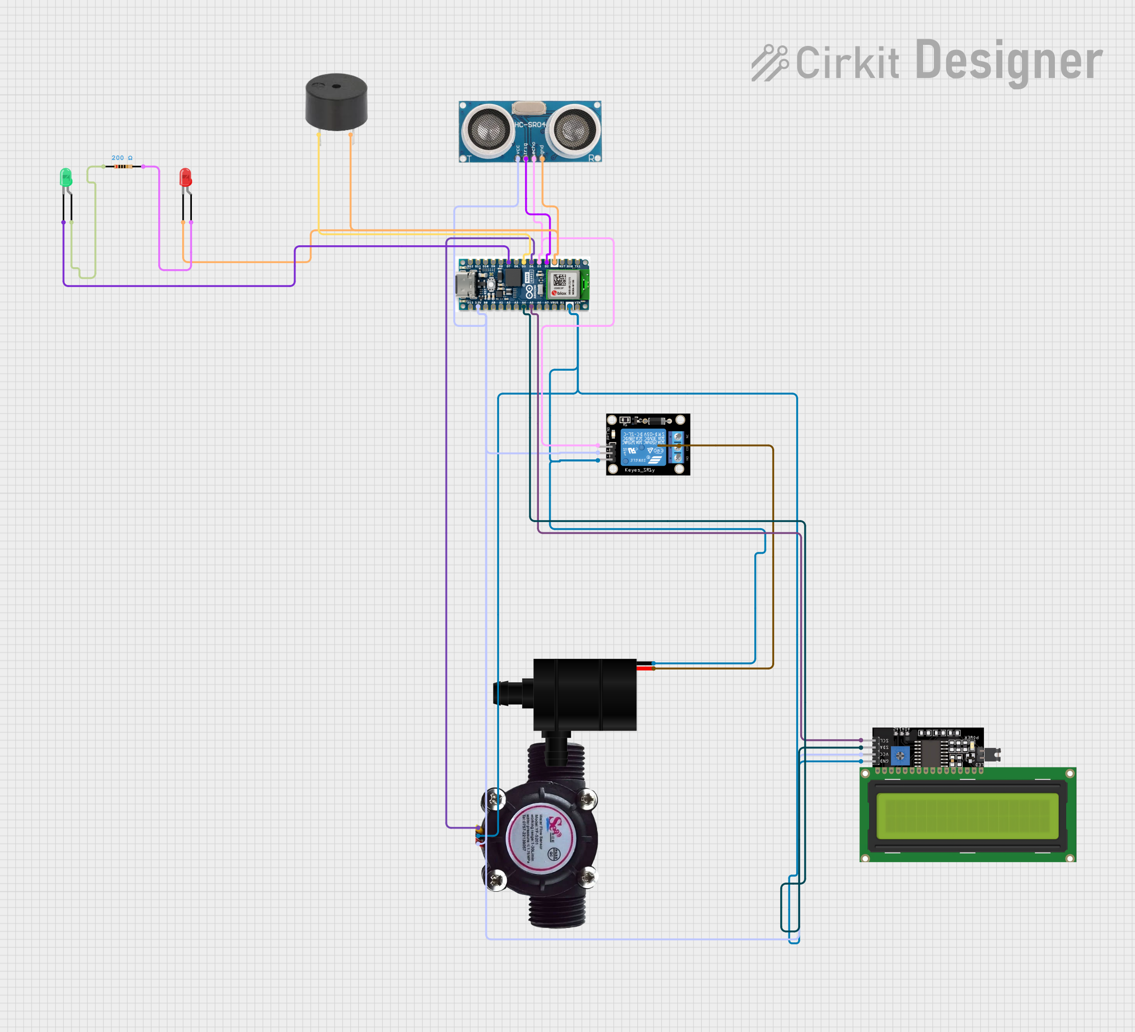
Water Tank Monitoring and Control System Documentation
Summary
This circuit is designed to monitor and control a water tank system. It features an ultrasonic sensor to measure water levels, an LCD display for status updates, a water flow sensor to ensure the pump's proper operation, a relay module to control a water pump, and indicators including a buzzer and LEDs for alerting about the water level status. The system is managed by an Arduino Nano ESP32 microcontroller, which processes the sensor data, controls the pump, and communicates with a mobile app for remote monitoring.
Component List
Water Flow Sensor
- Description: Measures the rate of water flow through a pipe.
- Pins: Signal, Vcc, GND
LCD Display 16x4 I2C
- Description: Displays information such as water level and system status.
- Pins: SCL, SDA, VCC, GND
KY-019 Relay Module 1 Channel
- Description: Controls the on/off state of the water pump.
- Pins: S, 5V, GND, NC, COM, NO
Water Pump
- Description: Pumps water into the tank when activated.
- Pins: VCC, GND
Arduino Nano ESP32
- Description: Microcontroller that orchestrates the sensor readings, controls the display, and manages the relay and indicators.
- Pins: Multiple digital and analog pins, power, and ground.
Ultrasonic Sensor
- Description: Measures the distance to the water surface, thus inferring the water level.
- Pins: +VCC, Trigger, Echo, GND
Buzzer
- Description: Emits an audible alert under certain conditions.
- Pins: PIN, GND
LED: Two Pin (Green)
- Description: Indicates the full water level status.
- Pins: Cathode, Anode
LED: Two Pin (Red)
- Description: Indicates the low water level status.
- Pins: Cathode, Anode
Resistor
- Description: Limits current to the LEDs.
- Value: 200 Ohms
- Pins: Pin1, Pin2
Wiring Details
Water Flow Sensor
- Signal -> Arduino Nano ESP32 (D4)
- Vcc -> Arduino Nano ESP32 (3.3V)
- GND -> Common Ground Net
LCD Display 16x4 I2C
- SCL -> Arduino Nano ESP32 (A5)
- SDA -> Arduino Nano ESP32 (A4)
- VCC -> Arduino Nano ESP32 (3.3V)
- GND -> Common Ground Net
KY-019 Relay Module 1 Channel
- S -> Arduino Nano ESP32 (D3)
- 5V -> Arduino Nano ESP32 (3.3V)
- GND -> Common Ground Net
- COM -> Water Pump (VCC)
Water Pump
- VCC -> KY-019 Relay Module (COM)
- GND -> Common Ground Net
Arduino Nano ESP32
- Multiple connections as detailed above.
- GND -> Common Ground Net
Ultrasonic Sensor
- +VCC -> Arduino Nano ESP32 (3.3V)
- Trigger -> Arduino Nano ESP32 (D2)
- Echo -> Arduino Nano ESP32 (D3)
- GND -> Common Ground Net
Buzzer
- PIN -> Arduino Nano ESP32 (D5)
- GND -> Common Ground Net
LED: Two Pin (Green)
- Cathode -> Arduino Nano ESP32 (D7)
- Anode -> Resistor (Pin1)
LED: Two Pin (Red)
- Cathode -> Common Ground Net
- Anode -> Resistor (Pin2)
Resistor
- Pin1 -> LED: Two Pin (Green) (Anode)
- Pin2 -> LED: Two Pin (Red) (Anode)
Documented Code
/*
 * This Arduino Sketch monitors and controls a water tank system.
 * It uses an ultrasonic sensor to measure water levels, displays the status on an LCD,
 * and sends updates to a mobile app. When the water level is low, it triggers a red LED
 * and a buzzer, then starts a water pump. When the tank is full, it stops the pump,
 * turns on a green LED, and sounds the buzzer. The water flow sensor ensures the pump
 * is working correctly.
 */

#include <Wire.h>
#include <LiquidCrystal_I2C.h>

// Pin definitions
#define WATER_FLOW_SENSOR_PIN 4
#define ULTRASONIC_TRIGGER_PIN 2
#define ULTRASONIC_ECHO_PIN 3
#define RELAY_PIN 3
#define BUZZER_PIN 5
#define RED_LED_PIN 7
#define GREEN_LED_PIN 6

// LCD setup
LiquidCrystal_I2C lcd(0x27, 16, 4);

void setup() {
  // Initialize serial communication
  Serial.begin(9600);

  // Initialize LCD
  lcd.begin();
  lcd.backlight();

  // Initialize pins
  pinMode(WATER_FLOW_SENSOR_PIN, INPUT);
  pinMode(ULTRASONIC_TRIGGER_PIN, OUTPUT);
  pinMode(ULTRASONIC_ECHO_PIN, INPUT);
  pinMode(RELAY_PIN, OUTPUT);
  pinMode(BUZZER_PIN, OUTPUT);
  pinMode(RED_LED_PIN, OUTPUT);
  pinMode(GREEN_LED_PIN, OUTPUT);

  // Initial states
  digitalWrite(RELAY_PIN, LOW);
  digitalWrite(BUZZER_PIN, LOW);
  digitalWrite(RED_LED_PIN, LOW);
  digitalWrite(GREEN_LED_PIN, LOW);
}

void loop() {
  // Measure water level
  int waterLevel = measureWaterLevel();

  // Display water level on LCD
  lcd.setCursor(0, 0);
  lcd.print("Water Level: ");
  lcd.print(waterLevel);

  if (waterLevel == 1) {
    // Low water level
    lcd.setCursor(0, 1);
    lcd.print("Status: Low");
    alertLowWaterLevel();
    startWaterPump();
  } else if (waterLevel == 6) {
    // Full water level
    lcd.setCursor(0, 1);
    lcd.print("Status: Full");
    stopWaterPump();
    alertFullWaterLevel();
  }

  // Monitor water flow
  monitorWaterFlow();

  // Delay for stability
  delay(1000);
}

int measureWaterLevel() {
  // Send trigger pulse
  digitalWrite(ULTRASONIC_TRIGGER_PIN, LOW);
  delayMicroseconds(2);
  digitalWrite(ULTRASONIC_TRIGGER_PIN, HIGH);
  delayMicroseconds(10);
  digitalWrite(ULTRASONIC_TRIGGER_PIN, LOW);

  // Measure echo pulse
  long duration = pulseIn(ULTRASONIC_ECHO_PIN, HIGH);
  int distance = duration * 0.034 / 2;

  // Convert distance to water level (1 to 6)
  if (distance < 10) return 6;
  else if (distance < 20) return 5;
  else if (distance < 30) return 4;
  else if (distance < 40) return 3;
  else if (distance < 50) return 2;
  else return 1;
}

void alertLowWaterLevel() {
  // Blink red LED and sound buzzer
  for (int i = 0; i < 5; i++) {
    digitalWrite(RED_LED_PIN, HIGH);
    digitalWrite(BUZZER_PIN, HIGH);
    delay(500);
    digitalWrite(RED_LED_PIN, LOW);
    digitalWrite(BUZZER_PIN, LOW);
    delay(500);
  }
  // Send low water level alert to mobile app
  Serial.println("Low water level!");
}

void alertFullWaterLevel() {
  // Turn on green LED and sound buzzer
  digitalWrite(GREEN_LED_PIN, HIGH);
  digitalWrite(BUZZER_PIN, HIGH);
  delay(5000);
  digitalWrite(GREEN_LED_PIN, LOW);
  digitalWrite(BUZZER_PIN, LOW);
  // Send full water level alert to mobile app
  Serial.println("Water tank full!");
}

void startWaterPump() {
  digitalWrite(RELAY_PIN, HIGH);
  Serial.println("Water pump started.");
}

void stopWaterPump() {
  digitalWrite(RELAY_PIN, LOW);
  Serial.println("Water pump stopped.");
}

void monitorWaterFlow() {
  int flowRate = digitalRead(WATER_FLOW_SENSOR_PIN);
  Serial.print("Water flow rate: ");
  Serial.println(flowRate);
  // Send water flow rate to mobile app
}
This code is responsible for the operation of the water tank monitoring and control system. It initializes the hardware components, takes measurements from the sensors, controls the water pump via the relay, and provides visual and audible alerts based on the water level. It also communicates with a mobile app to provide real-time updates on the system's status.