
Arduino and ESP-8266 Based Electrical Parameter Monitoring System with LCD Display
View and Edit Project In Cirkit Designer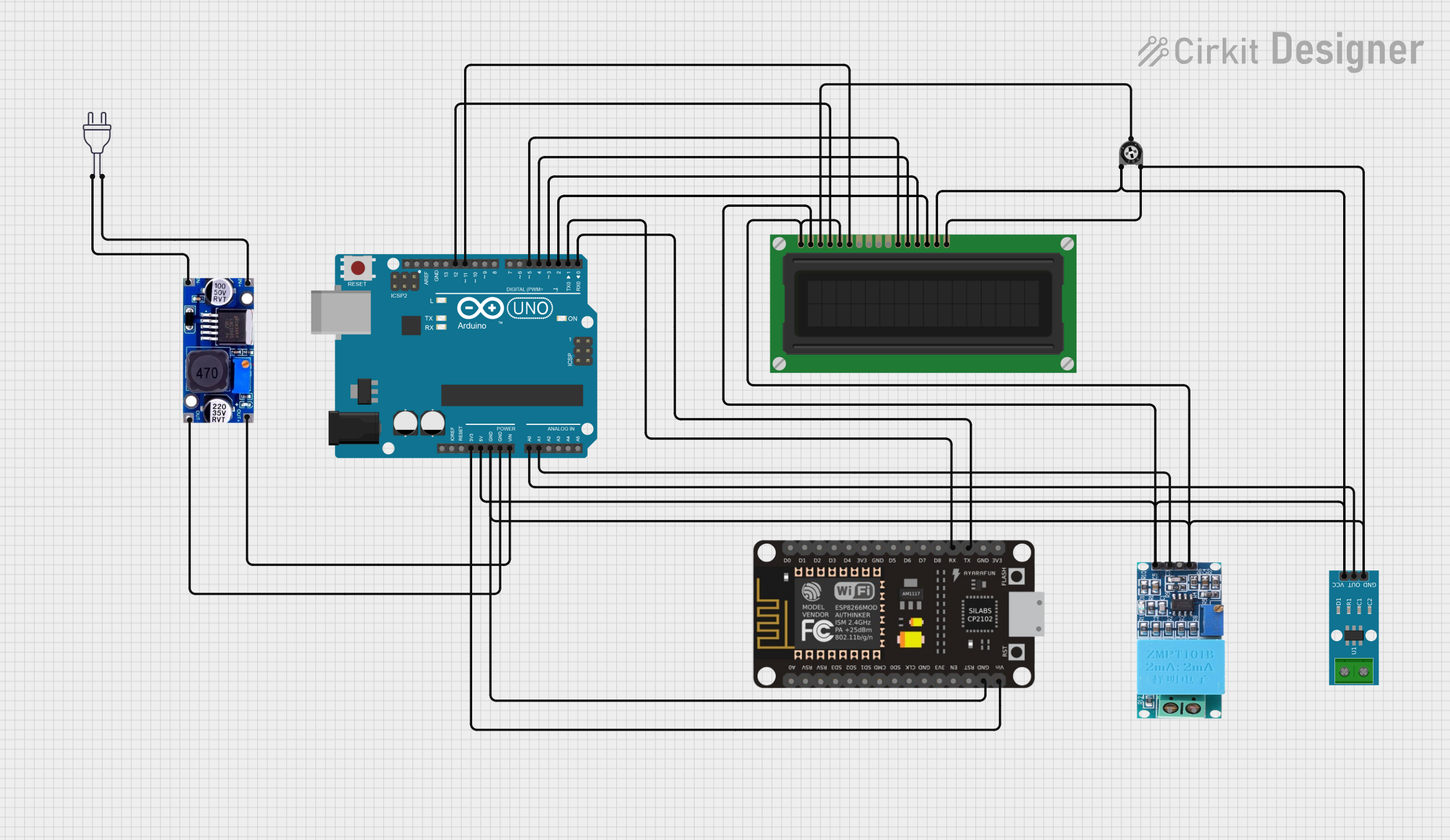
Circuit Documentation
Summary
This circuit integrates a variety of components to perform a specific set of functions. It includes an Arduino UNO as the main microcontroller, interfaced with an ESP-8266 Controller for Wi-Fi capabilities. The circuit also features an ACS712 Current Sensor and a ZMPT101B module for current and voltage sensing, respectively. An LCD Display is used for output visualization, and a Trimmer Potentiometer is included for adjustable settings. Power regulation is managed by an LM2596 module, and the circuit is powered by a 220V power source.
Component List
Arduino UNO
- Microcontroller board based on the ATmega328P
- Features digital I/O pins, analog input pins, and various power outputs
ACS712 Current Sensor 5A 20A 30A
- Hall-effect-based linear current sensor
- Capable of measuring both AC and DC currents
ZMPT101B
- Voltage Transformer module for measuring AC voltage
LCD Display (16 pin)
- Alphanumeric liquid crystal display
- Used for displaying data and messages to the user
Trimmer Potentiometer
- Variable resistor with three terminals
- Provides an adjustable voltage divider
ESP-8266 Controller
- Wi-Fi microchip with full TCP/IP stack and microcontroller capability
LM2596
- DC-DC buck converter module
- Used for stepping down voltage efficiently
Power 220V
- Main power source for the circuit
- Provides 220V AC which is then converted to the required DC voltages
Wiring Details
Arduino UNO
3.3Vconnected to ESP-8266 ControllerVin5Vconnected to:- Trimmer Potentiometer
leg1 - ACS712 Current Sensor
VCC - LCD Display
VDDandA - ZMPT101B
VCC
- Trimmer Potentiometer
GNDconnected to:- ESP-8266 Controller
GND - Trimmer Potentiometer
leg2 - ACS712 Current Sensor
GND - LCD Display
VSS,K, andR_W - ZMPT101B
GND
- ESP-8266 Controller
A0connected to ACS712 Current SensorOUTA1connected to ZMPT101BOUTD12connected to LCD DisplayRSD11connected to LCD DisplayED5connected to LCD DisplayDB4D4connected to LCD DisplayDB5D3connected to LCD DisplayDB6D2connected to LCD DisplayDB7D1connected to ESP-8266 ControllerRXD0connected to ESP-8266 ControllerTX
ACS712 Current Sensor
OUTconnected to Arduino UNOA0VCCconnected to Arduino UNO5VGNDconnected to Arduino UNOGND
ZMPT101B
OUTconnected to Arduino UNOA1VCCconnected to Arduino UNO5VGNDconnected to Arduino UNOGND
LCD Display (16 pin)
VDDandAconnected to Arduino UNO5VVSS,K, andR_Wconnected to Arduino UNOGNDRSconnected to Arduino UNOD12Econnected to Arduino UNOD11DB4connected to Arduino UNOD5DB5connected to Arduino UNOD4DB6connected to Arduino UNOD3DB7connected to Arduino UNOD2VOconnected to Trimmer Potentiometerwiper
Trimmer Potentiometer
leg1connected to Arduino UNO5Vwiperconnected to LCD DisplayVOleg2connected to Arduino UNOGND
ESP-8266 Controller
Vinconnected to Arduino UNO3.3VGNDconnected to Arduino UNOGNDRXconnected to Arduino UNOD1TXconnected to Arduino UNOD0
LM2596
INconnected to Power 220Vneutral wireandhot wireOUTconnected to Arduino UNOGNDandVin
Power 220V
neutral wireandhot wireconnected to LM2596IN
Documented Code
Arduino UNO Code (sketch.ino)
void setup() {
  // put your setup code here, to run once:

}

void loop() {
  // put your main code here, to run repeatedly:

}
Note: The provided code for the Arduino UNO is a template with empty setup and loop functions. The actual functionality needs to be implemented based on the specific requirements of the circuit.