
Arduino UNO and OV7670 Camera Module with Pushbutton Control
View and Edit Project In Cirkit Designer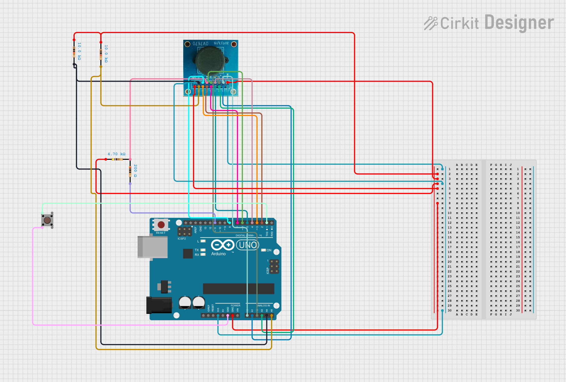
Circuit Documentation
Summary
This circuit involves an Arduino UNO microcontroller interfaced with an OV7670 camera module and a pushbutton. The camera module is powered on when the pushbutton is pressed. The circuit includes several resistors to manage voltage levels and ensure proper operation of the components.
Component List
Resistor (4700 Ohms)
- Pins: pin1, pin2
- Description: General-purpose resistor
- Purpose: Voltage regulation
Resistor (200 Ohms)
- Pins: pin1, pin2
- Description: General-purpose resistor
- Purpose: Voltage regulation
Arduino UNO
- Pins: UNUSED, IOREF, Reset, 3.3V, 5V, GND, Vin, A0, A1, A2, A3, A4, A5, SCL, SDA, AREF, D13, D12, D11, D10, D9, D8, D7, D6, D5, D4, D3, D2, D1, D0
- Description: Microcontroller board
- Purpose: Central control unit
OV7670 Camera Module
- Pins: RET, PWDN, D1, D0, D3, D2, D4, D5, D6, PLK, XLK, D7, VS, HS, SCL, SDA, 3.3V, DGND
- Description: Camera module
- Purpose: Capture images
Resistor (10000 Ohms)
- Pins: pin1, pin2
- Description: General-purpose resistor
- Purpose: Voltage regulation
Pushbutton
- Pins: Pin 3 (out), Pin 4 (out), Pin 1 (in), Pin 2 (in)
- Description: Momentary pushbutton switch
- Purpose: User input to control the camera module
Wiring Details
Resistor (4700 Ohms)
- pin1: Connected to OV7670 PWDN, OV7670 3.3V, Arduino UNO GND, Resistor (10000 Ohms) pin1
- pin2: Connected to OV7670 XLK
Resistor (200 Ohms)
- pin1: Not connected
- pin2: Connected to Arduino UNO D11
Arduino UNO
- 3.3V: Connected to OV7670 RET, OV7670 DGND
- GND: Connected to OV7670 PWDN, OV7670 3.3V, Resistor (10000 Ohms) pin1, Pushbutton Pin 2 (in)
- A0: Connected to OV7670 D0
- A1: Connected to OV7670 D1
- A2: Connected to OV7670 D2
- A3: Connected to OV7670 D3
- A4: Connected to Resistor (10000 Ohms) pin2, OV7670 SDA
- A5: Connected to Resistor (10000 Ohms) pin2, OV7670 SCL
- D11: Connected to Resistor (200 Ohms) pin2
- D8: Connected to OV7670 HS
- D7: Connected to OV7670 D7
- D6: Connected to OV7670 D6
- D5: Connected to OV7670 D5
- D4: Connected to OV7670 D4
- D3: Connected to OV7670 VS
- D2: Connected to OV7670 PLK
- D1: Connected to Pushbutton Pin 1 (in)
OV7670 Camera Module
- RET: Connected to Arduino UNO 3.3V
- PWDN: Connected to Resistor (4700 Ohms) pin1, Resistor (10000 Ohms) pin1, Arduino UNO GND
- D0: Connected to Arduino UNO A0
- D1: Connected to Arduino UNO A1
- D2: Connected to Arduino UNO A2
- D3: Connected to Arduino UNO A3
- D4: Connected to Arduino UNO D4
- D5: Connected to Arduino UNO D5
- D6: Connected to Arduino UNO D6
- D7: Connected to Arduino UNO D7
- PLK: Connected to Arduino UNO D2
- XLK: Connected to Resistor (4700 Ohms) pin2
- VS: Connected to Arduino UNO D3
- HS: Connected to Arduino UNO D8
- SCL: Connected to Resistor (10000 Ohms) pin2, Arduino UNO A5
- SDA: Connected to Resistor (10000 Ohms) pin2, Arduino UNO A4
- 3.3V: Connected to Resistor (4700 Ohms) pin1, Resistor (10000 Ohms) pin1, Arduino UNO GND
- DGND: Connected to Arduino UNO 3.3V
Resistor (10000 Ohms)
- pin1: Connected to OV7670 PWDN, OV7670 3.3V, Arduino UNO GND, Resistor (4700 Ohms) pin1
- pin2: Connected to Arduino UNO A4, OV7670 SDA, Arduino UNO A5, OV7670 SCL
Pushbutton
- Pin 1 (in): Connected to Arduino UNO D1
- Pin 2 (in): Connected to Arduino UNO GND
- Pin 3 (out): Not connected
- Pin 4 (out): Not connected
Code Documentation
/*
 * This Arduino sketch controls an OV7670 camera module. The camera is powered
 * on when a pushbutton is pressed. The pushbutton is connected to digital pin
 * D1 and the camera's power-down pin (PWDN) is connected to GND through a
 * resistor. The camera's other pins are connected to the Arduino as specified
 * in the circuit design.
 */

// Pin definitions
#define BUTTON_PIN 1  // Pin connected to the pushbutton
#define CAMERA_PWDN_PIN 7  // Pin connected to the camera's PWDN pin

void setup() {
  pinMode(BUTTON_PIN, INPUT);  // Set button pin as input
  pinMode(CAMERA_PWDN_PIN, OUTPUT);  // Set camera PWDN pin as output
  digitalWrite(CAMERA_PWDN_PIN, HIGH);  // Initially turn off the camera
}

void loop() {
  int buttonState = digitalRead(BUTTON_PIN);  // Read the button state
  if (buttonState == HIGH) {
    digitalWrite(CAMERA_PWDN_PIN, LOW);  // Turn on the camera
  } else {
    digitalWrite(CAMERA_PWDN_PIN, HIGH);  // Turn off the camera
  }
  delay(100);  // Debounce delay
}
This code initializes the pushbutton and camera power-down pin, and continuously checks the state of the pushbutton to control the power state of the camera. When the button is pressed, the camera is powered on; otherwise, it remains off.