ESP32-CAM Wi-Fi Controlled Robot with L298N Motor Driver
Circuit Documentation
Summary
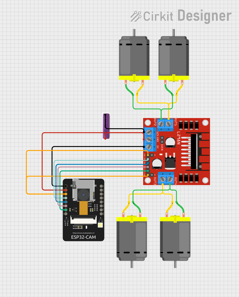
The circuit in question is designed to control a set of DC motors using an L298N DC motor driver, which is interfaced with an ESP32-CAM microcontroller. The ESP32-CAM also handles wireless communication and camera functionalities. The motors are powered by a 3.7V battery, and the system is capable of driving the motors in different directions based on the commands received from a web interface.
Component List
L298N DC Motor Driver
- Description: A motor driver module capable of driving two DC motors.
- Pins: OUT1, OUT2, 12V, GND, 5V, OUT3, OUT4, 5V-ENA-JMP-I, 5V-ENA-JMP-O, +5V-J1, +5V-J2, ENA, IN1, IN2, IN3, IN4, ENB
ESP32 - CAM
- Description: A microcontroller with integrated Wi-Fi and camera functionalities.
- Pins: 5V, GND, IO12, IO13, IO15, IO14, IO2, IO4, VOT, VOR, VCC, IO0, IO16, 3V3
3.7V Battery
- Description: A power source for the circuit.
- Pins: +, -
DC Motors
- Description: Four identical DC motors used for motion.
- Pins: pin 1, pin 2
Wiring Details
L298N DC Motor Driver
- 12V: Connected to the negative terminal (-) of the 3.7V battery.
- GND: Connected to the ground (GND) of the ESP32-CAM and the positive terminal (+) of the 3.7V battery.
- 5V: Connected to the 5V of the ESP32-CAM.
- OUT1, OUT2: Connected to two DC motors (Motor A).
- OUT3, OUT4: Connected to two other DC motors (Motor B).
- ENA, ENB: Connected to IO12 of the ESP32-CAM.
- IN1: Connected to IO13 of the ESP32-CAM.
- IN2: Connected to IO15 of the ESP32-CAM.
- IN3: Connected to IO14 of the ESP32-CAM.
- IN4: Connected to IO2 of the ESP32-CAM.
ESP32 - CAM
- 5V: Connected to the 5V of the L298N DC motor driver.
- GND: Connected to the GND of the L298N DC motor driver and the positive terminal (+) of the 3.7V battery.
- IO12: Connected to ENA and ENB of the L298N DC motor driver.
- IO13: Connected to IN1 of the L298N DC motor driver.
- IO15: Connected to IN2 of the L298N DC motor driver.
- IO14: Connected to IN3 of the L298N DC motor driver.
- IO2: Connected to IN4 of the L298N DC motor driver.
3.7V Battery
- + (Positive): Connected to the GND of the L298N DC motor driver and the GND of the ESP32-CAM.
- - (Negative): Connected to the 12V of the L298N DC motor driver.
DC Motors
- Motor A (Two Motors): One motor's pin 1 connected to OUT1 and pin 2 to OUT2 of the L298N DC motor driver. The other motor's pin 1 connected to OUT2 and pin 2 to OUT1.
- Motor B (Two Motors): One motor's pin 1 connected to OUT3 and pin 2 to OUT4 of the L298N DC motor driver. The other motor's pin 1 connected to OUT4 and pin 2 to OUT3.
Documented Code
The code for the ESP32-CAM microcontroller is written in C++ and is designed to handle web server functionality, WebSocket communication, motor control, and camera streaming. The code is structured as follows:
- Includes and Definitions: The necessary libraries and definitions for the camera, Wi-Fi, and motor control are included at the beginning of the code.
- Global Variables: Variables for motor pins, PWM settings, camera settings, Wi-Fi credentials, and WebSocket servers are declared.
- HTML Page: An HTML page is defined as a string literal, which will be served to clients connecting to the ESP32-CAM's IP address. It includes controls for the car's movement and light.
- Motor Control Functions: Functions to rotate the motors in different directions and to move the car based on the input received from the web interface.
- WebSocket Event Handlers: Functions to handle events for the camera and car input WebSocket connections.
- Camera Setup: Function to initialize the camera with the specified configuration.
- Web Server Handlers: Functions to handle HTTP GET requests for the root page and 404 errors.
- Setup Function: The
setup()function initializes pin modes, starts the serial communication, sets up the Wi-Fi access point, starts the web server, and initializes the camera. - Loop Function: The
loop()function continuously cleans up WebSocket clients and sends camera pictures to the connected client.
The code is designed to be uploaded to the ESP32-CAM microcontroller and will execute upon powering the device. It enables the ESP32-CAM to act as a Wi-Fi access point, serve a web page for control, and stream camera data while responding to WebSocket messages to control the motors' speed and direction.