
Battery-Powered Line Following Robot with L298N Motor Driver and KY-033 Sensors
View and Edit Project In Cirkit Designer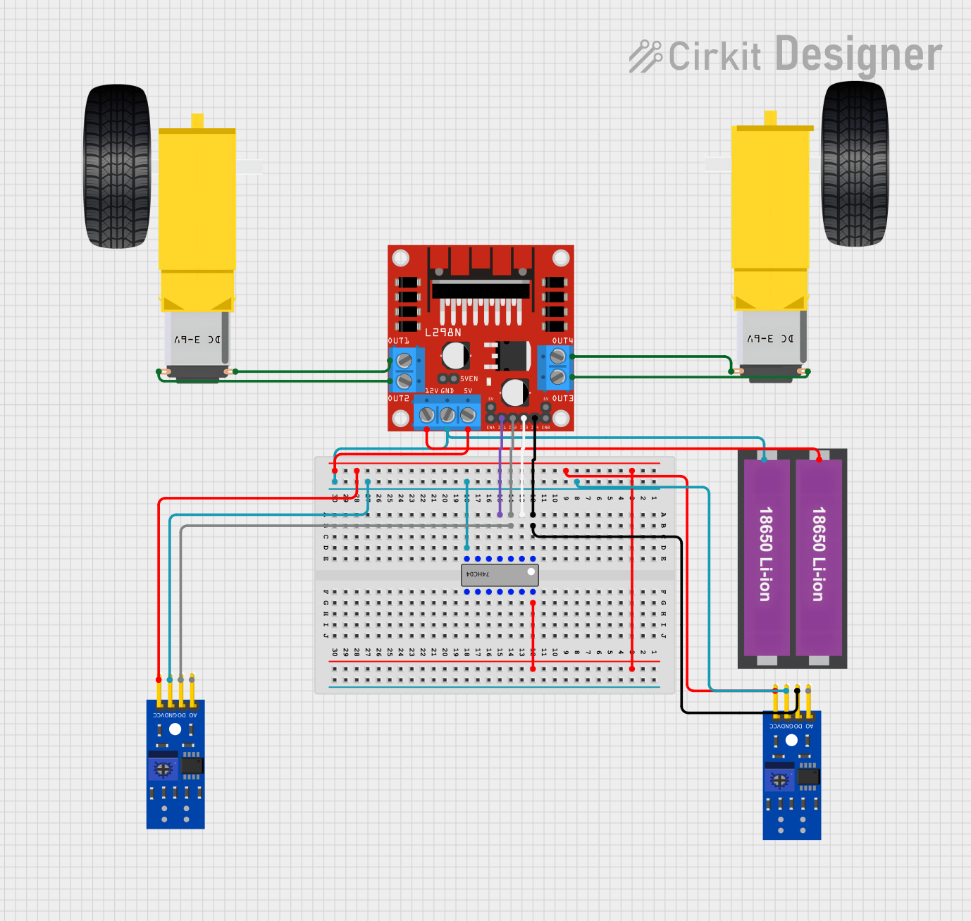
Circuit Documentation
Summary
This document provides a detailed overview of a circuit designed to control a pair of DC motors using an L298N motor driver, two KY-033 line tracking sensors, and a 74HC04 hex inverter. The circuit is powered by two 18650 Li-ion batteries. The document includes a component list, wiring details, and code documentation.
Component List
L298N DC Motor Driver
- Description: A dual H-bridge motor driver that allows control of the speed and direction of two DC motors.
- Pins: OUT1, OUT2, 12V, GND, 5V, OUT3, OUT4, 5V-ENA-JMP-I, 5V-ENA-JMP-O, +5V-J1, +5V-J2, ENA, IN1, IN2, IN3, IN4, ENB
KY-033 Line Tracking Sensor (2 units)
- Description: A sensor module used for line tracking in robotics.
- Pins: A0, D0, GND, VCC
74HC04
- Description: A hex inverter IC used to invert the logic levels of input signals.
- Pins: A1, Y1, A2, Y2, A3, Y3, GND, VCC, A6, Y6, A5, Y5, A4, Y4
18650 Li-ion Battery x 2
- Description: A pair of rechargeable lithium-ion batteries used to power the circuit.
- Pins: +, -
Gearmotor DC Wheels Left
- Description: A DC motor with attached wheels for the left side of a robot.
- Pins: PIN1, PIN2
Gearmotor DC Wheels Right
- Description: A DC motor with attached wheels for the right side of a robot.
- Pins: PIN1, PIN2
Wiring Details
L298N DC Motor Driver
- OUT1 connected to PIN2 of Gearmotor DC Wheels Right
- OUT2 connected to PIN1 of Gearmotor DC Wheels Right
- OUT3 connected to PIN2 of Gearmotor DC Wheels Left
- OUT4 connected to PIN1 of Gearmotor DC Wheels Left
- 12V connected to + of 18650 Li-ion Battery x 2
- GND connected to - of 18650 Li-ion Battery x 2, GND of KY-033 Line Tracking Sensor (both units), and GND of 74HC04
- 5V connected to VCC of KY-033 Line Tracking Sensor (both units) and VCC of 74HC04
- IN1 connected to Y2 of 74HC04
- IN2 connected to A2 of 74HC04 and D0 of KY-033 Line Tracking Sensor (second unit)
- IN3 connected to Y1 of 74HC04
- IN4 connected to A1 of 74HC04 and D0 of KY-033 Line Tracking Sensor (first unit)
KY-033 Line Tracking Sensor (First Unit)
- GND connected to GND of L298N DC Motor Driver
- VCC connected to 5V of L298N DC Motor Driver
- D0 connected to A1 of 74HC04
- A0 not connected
KY-033 Line Tracking Sensor (Second Unit)
- GND connected to GND of L298N DC Motor Driver
- VCC connected to 5V of L298N DC Motor Driver
- D0 connected to A2 of 74HC04
- A0 not connected
74HC04
- GND connected to GND of L298N DC Motor Driver
- VCC connected to 5V of L298N DC Motor Driver
- Y2 connected to IN1 of L298N DC Motor Driver
- A2 connected to IN2 of L298N DC Motor Driver and D0 of KY-033 Line Tracking Sensor (second unit)
- Y1 connected to IN3 of L298N DC Motor Driver
- A1 connected to IN4 of L298N DC Motor Driver and D0 of KY-033 Line Tracking Sensor (first unit)
18650 Li-ion Battery x 2
- + connected to 12V of L298N DC Motor Driver
- - connected to GND of L298N DC Motor Driver
Gearmotor DC Wheels Left
- PIN1 connected to OUT4 of L298N DC Motor Driver
- PIN2 connected to OUT3 of L298N DC Motor Driver
Gearmotor DC Wheels Right
- PIN1 connected to OUT2 of L298N DC Motor Driver
- PIN2 connected to OUT1 of L298N DC Motor Driver
Code Documentation
No code is provided for this circuit.
This document provides a comprehensive overview of the circuit, including a summary, component list, wiring details, and code documentation. The detailed wiring information ensures that each component is correctly connected, facilitating the assembly and troubleshooting of the circuit.