
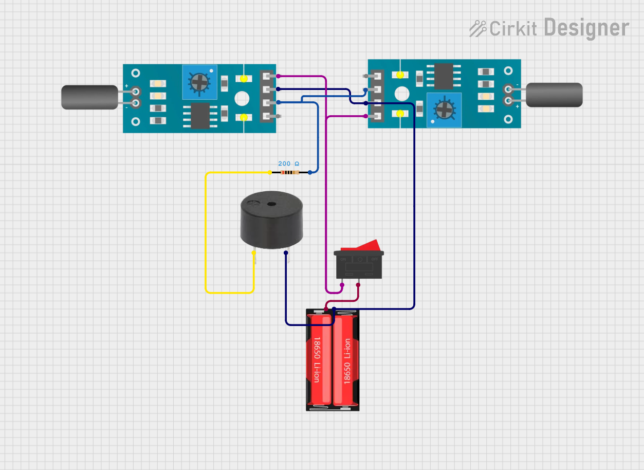
Circuit Documentation
Summary
This circuit consists of two tilt sensors, a buzzer, a rocker switch, a 18650 Li-Ion battery, and a resistor. The circuit is designed to detect tilt using the sensors and trigger the buzzer when a tilt is detected. The rocker switch is used to control the power supply from the 18650 Li-Ion battery.
Component List
Tilt Sensor
- Pins: A0, D0, GND, VCC
- Description: Detects tilt and outputs a digital signal.
- Purpose in Circuit: Senses tilt and sends a signal to the buzzer.
Buzzer
- Pins: PIN, GND
- Description: Emits sound when activated.
- Purpose in Circuit: Alerts when tilt is detected.
Rocker Switch
- Pins: 1, 2
- Description: A switch to control the power supply.
- Purpose in Circuit: Turns the circuit on or off.
18650 Li-Ion Battery
- Pins: Positive, Negative
- Description: Provides power to the circuit.
- Purpose in Circuit: Supplies power to all components.
Resistor
- Pins: pin1, pin2
- Description: 200 Ohms resistor.
- Purpose in Circuit: Limits current to the buzzer.
Wiring Details
Tilt Sensor 1
Pin D0 is connected to:
- Tilt Sensor 2 Pin D0
- Resistor Pin pin2
Pin GND is connected to:
- Buzzer Pin GND
- 18650 Li-Ion Battery Pin Negative
- Tilt Sensor 2 Pin GND
Pin VCC is connected to:
- Rocker Switch Pin 1
- Tilt Sensor 2 Pin VCC
Tilt Sensor 2
Pin D0 is connected to:
- Tilt Sensor 1 Pin D0
- Resistor Pin pin2
Pin GND is connected to:
- Buzzer Pin GND
- 18650 Li-Ion Battery Pin Negative
- Tilt Sensor 1 Pin GND
Pin VCC is connected to:
- Rocker Switch Pin 1
- Tilt Sensor 1 Pin VCC
Buzzer
Pin GND is connected to:
- Tilt Sensor 1 Pin GND
- 18650 Li-Ion Battery Pin Negative
- Tilt Sensor 2 Pin GND
Pin PIN is connected to:
- Resistor Pin pin1
Rocker Switch
Pin 1 is connected to:
- Tilt Sensor 1 Pin VCC
- Tilt Sensor 2 Pin VCC
Pin 2 is connected to:
- 18650 Li-Ion Battery Pin Positive
18650 Li-Ion Battery
Pin Positive is connected to:
- Rocker Switch Pin 2
Pin Negative is connected to:
- Tilt Sensor 1 Pin GND
- Buzzer Pin GND
- Tilt Sensor 2 Pin GND
Resistor
Pin pin1 is connected to:
- Buzzer Pin PIN
Pin pin2 is connected to:
- Tilt Sensor 1 Pin D0
- Tilt Sensor 2 Pin D0
Code
There is no code provided for this circuit.