
Arduino Nano Controlled LCD Interface with Pushbutton Inputs
View and Edit Project In Cirkit Designer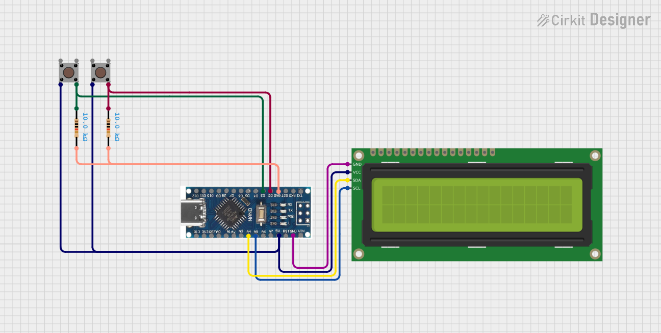
Circuit Documentation
Summary of the Circuit
This circuit is designed to interface a 16x2 I2C LCD with a Nano 3.0 ATmega328P Type-C USB CH340 Controller Board. The LCD is used for displaying information, and two pushbuttons are included, each with a pull-up resistor to ensure a defined logic level when the button is not pressed. The buttons are likely used for user input to interact with the system. The I2C communication protocol is used to minimize the number of pins required for the LCD, utilizing only two data lines (SDA and SCL). The circuit is powered by the 5V output from the Nano board, which also provides ground connections to the LCD and the resistors associated with the pushbuttons.
Component List
Nano 3.0 ATmega328P Type-C USB CH340 Controller Board
- Microcontroller board based on the ATmega328P
- Features a variety of digital and analog pins
- Equipped with a Type-C USB for programming and power
- Operates at 5V
16x2 I2C LCD
- A liquid crystal display capable of showing 2 lines of 16 characters
- Uses the I2C protocol for communication, reducing the number of required pins
- Requires power (VCC) and ground (GND) connections
Pushbutton (x2)
- A simple switch that connects two contacts when pressed
- Typically used for user input
Resistor (x2)
- A 10,000 Ohm resistor
- Likely used as a pull-up resistor for the pushbuttons
Wiring Details
Nano 3.0 ATmega328P Type-C USB CH340 Controller Board
- A4 (SDA) connected to the SDA pin of the 16x2 I2C LCD
- A5 (SCL) connected to the SCL pin of the 16x2 I2C LCD
- 5V connected to the VCC pin of the 16x2 I2C LCD and to one side of the pushbuttons
- GND connected to the GND pin of the 16x2 I2C LCD and to one side of the 10,000 Ohm resistors
- D3 connected to one side of a 10,000 Ohm resistor, which is connected to a pushbutton
- D2 connected to one side of a 10,000 Ohm resistor, which is connected to another pushbutton
16x2 I2C LCD
- SDA connected to A4 (SDA) on the Nano board
- SCL connected to A5 (SCL) on the Nano board
- VCC connected to 5V on the Nano board
- GND connected to GND on the Nano board
Pushbutton
- One side connected to 5V on the Nano board
- The other side connected to a 10,000 Ohm resistor and then to a digital pin (D2 or D3) on the Nano board
Resistor (10,000 Ohms)
- One side connected to a pushbutton
- The other side connected to GND on the Nano board and to a digital pin (D2 or D3) on the Nano board
Documented Code
No code was provided for the microcontroller. To fully utilize this circuit, embedded code for the Nano 3.0 ATmega328P Type-C USB CH340 Controller Board is required. The code should initialize the I2C communication for the LCD, set up the digital pins connected to the pushbuttons as inputs with internal pull-up resistors, and include logic for button press detection and LCD display updates.