Cirkit Designer
Your all-in-one circuit design IDE
Home /
Project Documentation
Arduino-Controlled IR Remote Relay with Visual Indicators
Circuit Documentation
Summary
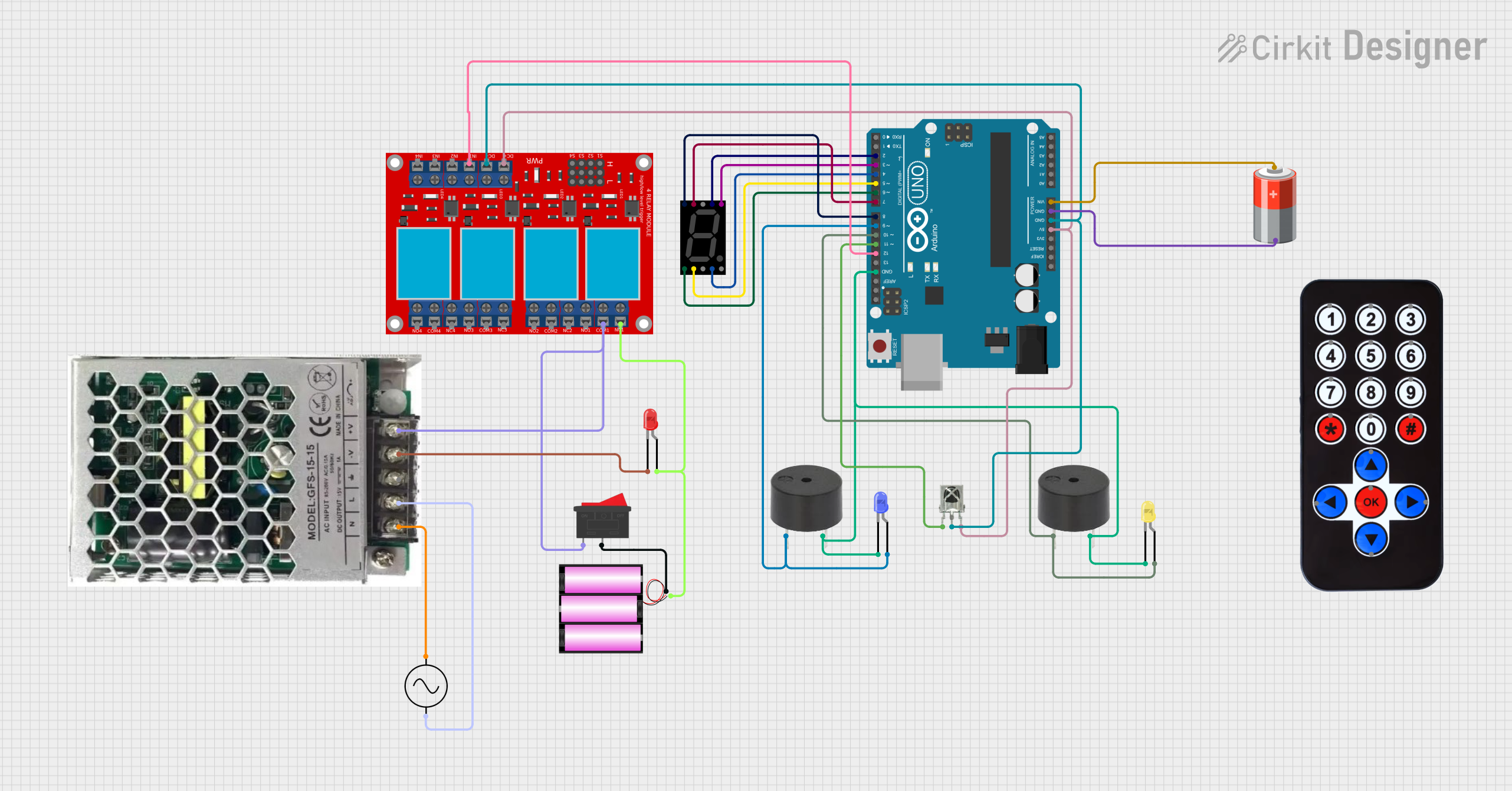
This document provides a detailed overview of a circuit designed to interface with various components including a seven-segment display, buzzers, LEDs, an IR receiver, a relay module, and an Arduino UNO microcontroller. The circuit is powered by a 5V battery and a 12V battery, with voltage regulation provided by an SMPS (Switched-Mode Power Supply). The Arduino UNO is used as the central processing unit to control the components based on the inputs received from the IR receiver and to drive the display and indicators (LEDs and buzzers).
Component List
Seven Segment Display (Wokwi Compatible)
- A display device used to show numerical digits and capable of displaying a decimal point.
Buzzer
- An audible signaling device that can be used to provide alerts or feedback to the user.
LED: Two Pin (blue)
- A blue light-emitting diode used as an indicator or for illumination.
LED: Two Pin (yellow)
- A yellow light-emitting diode used as an indicator or for illumination.
VS1838B IR Receiver
- An infrared receiver that captures signals from an IR remote control.
HX1838 Infared IR Wireless Remote Control
- A remote control that sends signals to the IR receiver to trigger different actions in the circuit.
4 Channel Relay Module
- A module with four relays that can control the high power or high voltage devices.
SMPS_9V_UP15S09
- A switched-mode power supply that converts AC to a 9V DC output.
LED: Two Pin (red)
- A red light-emitting diode used as an indicator or for illumination.
Battery 12V
- A 12V battery used to provide power to the circuit.
Rocker Switch
- A switch used to control the power supply to the circuit.
AC Supply
- The main AC power source for the SMPS.
5V Battery
- A 5V battery used to power the Arduino UNO.
Arduino UNO
- A microcontroller board based on the ATmega328P, used as the main controller for the circuit.
Wiring Details
Seven Segment Display (Wokwi Compatible)
- Segments A-G and DP connected to digital pins D2-D9 on the Arduino UNO.
Buzzer
- One buzzer's GND connected to the common ground.
- Another buzzer's GND connected to the common ground and PIN connected to digital pin D10 on the Arduino UNO.
LED: Two Pin (blue)
- Cathode connected to the common ground.
- Anode connected to digital pin D9 on the Arduino UNO.
LED: Two Pin (yellow)
- Cathode connected to the common ground.
- Anode connected to digital pin D10 on the Arduino UNO.
VS1838B IR Receiver
- OUT connected to digital pin D11 on the Arduino UNO.
- VCC connected to the 5V output from the Arduino UNO.
- GND connected to the common ground.
4 Channel Relay Module
- IN 1 connected to digital pin D12 on the Arduino UNO.
- VCC+ connected to the 5V output from the Arduino UNO.
- VCC- (GND) connected to the common ground.
- COM 1 connected to the output of the SMPS_9V_UP15S09.
- N.C. 1 connected to the anode of the red LED and the cathode connected to the -V output of the SMPS_9V_UP15S09.
SMPS_9V_UP15S09
- Neutral connected to the -ve of the AC Supply.
- Live connected to the +ve of the AC Supply.
- GND connected to the common ground.
- +V connected to the COM 1 of the relay module.
LED: Two Pin (red)
- Cathode connected to the -V output of the SMPS_9V_UP15S09.
- Anode connected to the N.C. 1 of the relay module.
Battery 12V
- connected to one side of the Rocker Switch.
- connected to the N.C. 1 of the relay module.
Rocker Switch
- One side connected to the + of the 12V battery.
- Other side connected to the COM 1 of the relay module.
5V Battery
- connected to the Vin of the Arduino UNO.
- connected to the common ground.
Documented Code
Arduino UNO Code (sketch.ino)
void setup() {
  // put your setup code here, to run once:

}

void loop() {
  // put your main code here, to run repeatedly:

}
Note: The provided code is a template and does not contain any functional code. It needs to be populated with the logic to control the circuit based on the requirements.