Raspberry Pi and Arduino Uno Controlled Relay System with Current Sensing
Circuit Documentation
Summary
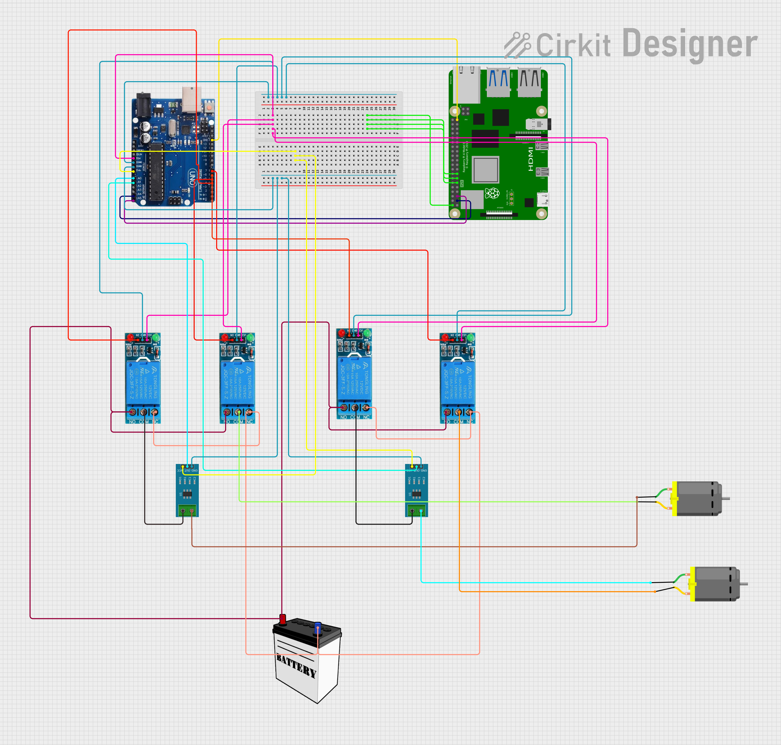
The circuit in question is a complex system that integrates a Raspberry Pi 4B with an Arduino Uno R3, multiple 12V single-channel relays, current sensors, a 12V battery, and DC motors. The Raspberry Pi and Arduino Uno are used for control logic and sensor data processing. The relays act as switches for the DC motors, allowing the microcontrollers to turn the motors on and off. The current sensors are used to monitor the current flowing through the motors, and the 12V battery provides power to the system.
Component List
Raspberry Pi 4B
- A microcomputer with multiple GPIO pins used for controlling and interfacing with other components in the circuit.
Arduino Uno R3
- A microcontroller board based on the ATmega328P, used for interfacing with sensors, relays, and providing I2C communication with the Raspberry Pi.
12V Single Channel Relay
- An electrically operated switch that allows the Arduino Uno to control high power devices such as DC motors.
Current Sensor 5A
- A sensor used to measure the electric current in a circuit.
12V Battery
- The power source for the relays and the DC motors.
DC Motor
- An electric motor powered by the 12V battery and controlled by the relays.
Wiring Details
Raspberry Pi 4B
5V- Power supply for the Raspberry Pi.GPIO17,GPIO27,GPIO22- General purpose input/output pins (exact functions not specified).GPIO2- Connected to Arduino Uno'sA4/SDAfor I2C data line.GPIO3- Connected to Arduino Uno'sA5/SCLfor I2C clock line.GND- Ground connection, shared with Arduino Uno.
Arduino Uno R3
GND- Ground connection, shared with Raspberry Pi and relays.5V- Connected to the VCC of all relays to supply power.VIN- Connected to the VCC of both current sensors to supply power.A0,A1- Analog inputs connected to the output of the current sensors.7,6,5,4- Digital outputs connected to the input of the relays to control them.
12V Single Channel Relay
GND- Ground connection, shared with Arduino Uno.VCC- Power supply from Arduino Uno's5V.IN- Control input from Arduino Uno's digital pins7,6,5,4.NC,COM,NO- Relay switch terminals connected to the battery and motors as per the control logic.
Current Sensor 5A
GND- Ground connection, shared with Arduino Uno.VCC- Power supply from Arduino Uno'sVIN.OUT- Output connected to Arduino Uno's analog pinsA0,A1.1,2- Current input/output connected to the relay'sCOMand the motors.
12V Battery
VCC- Positive terminal connected to theNOof the relays.GND- Negative terminal connected to theNCof the relays.
DC Motor
pin 1,pin 2- Connected to the current sensors and theCOMof the relays.
Documented Code
There is no code provided for the microcontrollers in the circuit. The documentation of the code would typically include descriptions of the functions, algorithms, and logic used to control the components in the circuit. Since no code is available, this section cannot be completed.