Cirkit Designer
Your all-in-one circuit design IDE
Home /
Project Documentation
ESP32-Based Smart Scale with LCD Display and Piezo Speaker
Circuit Documentation
Summary
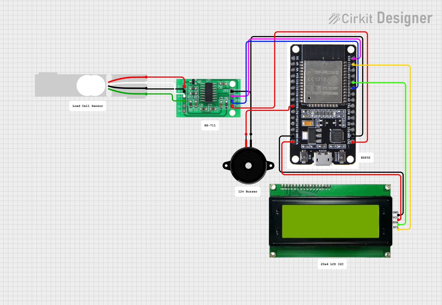
This document provides a detailed overview of a circuit that includes a Piezo Speaker, a Load Cell, an LCD2004 I2C Module, an HX711 Bridge Sensor Interface, and an ESP32 microcontroller. The circuit is designed to interface a load cell with an ESP32, display data on an LCD, and provide audio feedback through a Piezo Speaker.
Component List
Piezo Speaker
- Description: A simple piezoelectric speaker used for generating sound.
- Pins: pin1, pin2
Load Cell - Red/white/black/green
- Description: A load cell sensor used for measuring weight.
- Pins: E+, A-, E-, A+
MKE-M08 LCD2004 I2C Module
- Description: An LCD module with I2C interface for displaying data.
- Pins: GND, 5V, SDA, SCL
HX711 - Bridge Sensor Interface
- Description: An interface module for connecting bridge sensors like load cells.
- Pins: E+, E-, A-, A+, B-, B+, GND - GROUND, DATA (OUT), SCK - CLOCK (IN), 3.3/3.5V Supply
ESP32
- Description: A powerful microcontroller with Wi-Fi and Bluetooth capabilities.
- Pins: EN, VP, VN, D34, D35, D32, D33, D25, D26, D27, D14, D12, D13, GND, VIN, 3V3, D15, D2, D4, RX2, TX2, D5, D18, D19, D21, RX0, TX0, D22, D23, BOOT
Wiring Details
Piezo Speaker
- pin2 is connected to ESP32 D26
- pin1 is connected to ESP32 GND and HX711 GND - GROUND
Load Cell - Red/white/black/green
- E+ is connected to HX711 E+
- E- is connected to HX711 E-
- A- is connected to HX711 A-
- A+ is connected to HX711 A+
MKE-M08 LCD2004 I2C Module
- GND is connected to ESP32 GND
- 5V is connected to ESP32 VIN
- SDA is connected to ESP32 D21
- SCL is connected to ESP32 D22
HX711 - Bridge Sensor Interface
- 3.3/3.5V Supply is connected to ESP32 3V3
- GND - GROUND is connected to Piezo Speaker pin1 and ESP32 GND
- SCK - CLOCK (IN) is connected to ESP32 D19
- DATA (OUT) is connected to ESP32 D23
- E+ is connected to Load Cell E+
- E- is connected to Load Cell E-
- A- is connected to Load Cell A-
- A+ is connected to Load Cell A+
ESP32
- D26 is connected to Piezo Speaker pin2
- GND is connected to Piezo Speaker pin1, HX711 GND - GROUND, and MKE-M08 LCD2004 I2C Module GND
- VIN is connected to MKE-M08 LCD2004 I2C Module 5V
- 3V3 is connected to HX711 3.3/3.5V Supply
- D19 is connected to HX711 SCK - CLOCK (IN)
- D21 is connected to MKE-M08 LCD2004 I2C Module SDA
- D22 is connected to MKE-M08 LCD2004 I2C Module SCL
- D23 is connected to HX711 DATA (OUT)
Code
No code is provided for this circuit.