
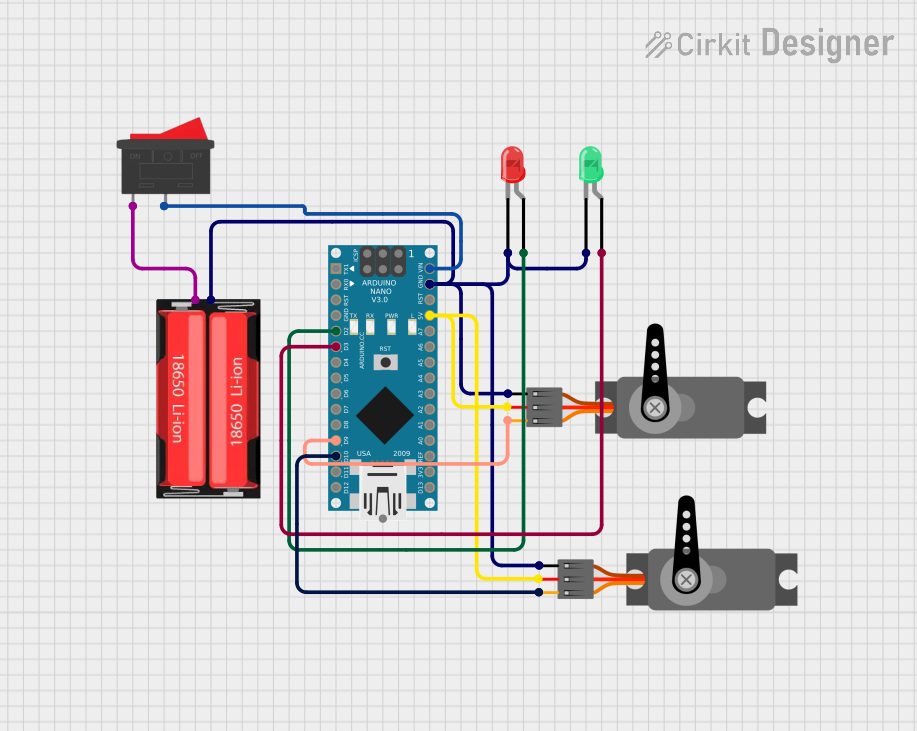
Circuit Documentation
Summary of the Circuit
This circuit appears to be designed for controlling two servo motors and monitoring the state of two LEDs (one green and one red). The control and monitoring are managed by an Arduino Nano microcontroller. A rocker switch is used to control the power supply from a single 18650 Li-Ion battery to the Arduino Nano. The Arduino Nano then distributes power to the servo motors and controls the LEDs and servos via its digital pins.
Component List
Rocker Switch
- Description: A simple on/off switch that controls the connection between the power source and the rest of the circuit.
Arduino Nano
- Description: A compact microcontroller board based on the ATmega328P, equipped with a variety of digital and analog pins for interfacing with various components.
18650 Li-Ion Battery
- Description: A rechargeable lithium-ion cell commonly used in portable electronics, providing a power source for the circuit.
Servo (x2)
- Description: An actuator capable of precise position control, commonly used in robotics and RC vehicles.
LED: Two Pin (green)
- Description: A green light-emitting diode that can be used as an indicator light.
LED: Two Pin (red)
- Description: A red light-emitting diode that can be used as an indicator light.
Wiring Details
Rocker Switch
- Connections:
- One side connected to the positive terminal of the 18650 Li-Ion battery.
- The other side connected to the VIN pin of the Arduino Nano.
Arduino Nano
- Power Connections:
- VIN connected to the Rocker Switch.
- GND connected to the common ground net, which includes the cathodes of both LEDs, the GND pins of both servos, and the negative terminal of the 18650 Li-Ion battery.
- 5V pin providing power to the VCC pins of both servos.
- Control Connections:
- D2 controlling the anode of the red LED.
- D3 controlling the anode of the green LED.
- D9 connected to the PWM input of one servo.
- D10 connected to the PWM input of the other servo.
18650 Li-Ion Battery
- Connections:
- Positive terminal connected to the Rocker Switch.
- Negative terminal connected to the common ground net.
Servo (x2)
- Connections:
- GND connected to the common ground net.
- VCC connected to the 5V output from the Arduino Nano.
- PWM input connected to either D9 or D10 on the Arduino Nano for control signals.
LED: Two Pin (green)
- Connections:
- Anode connected to D3 on the Arduino Nano.
- Cathode connected to the common ground net.
LED: Two Pin (red)
- Connections:
- Anode connected to D2 on the Arduino Nano.
- Cathode connected to the common ground net.
Documented Code
Arduino Nano Code (sketch.ino)
void setup() {
  // put your setup code here, to run once:

}

void loop() {
  // put your main code here, to run repeatedly:

}
Note: The provided code is a template and does not contain any functional code for controlling the LEDs or servos. The user will need to add the appropriate code within the setup() and loop() functions to control the components as intended.