
Arduino UNO-Based Alcohol Detection System with Bluetooth Connectivity and Visual Alerts
View and Edit Project In Cirkit Designer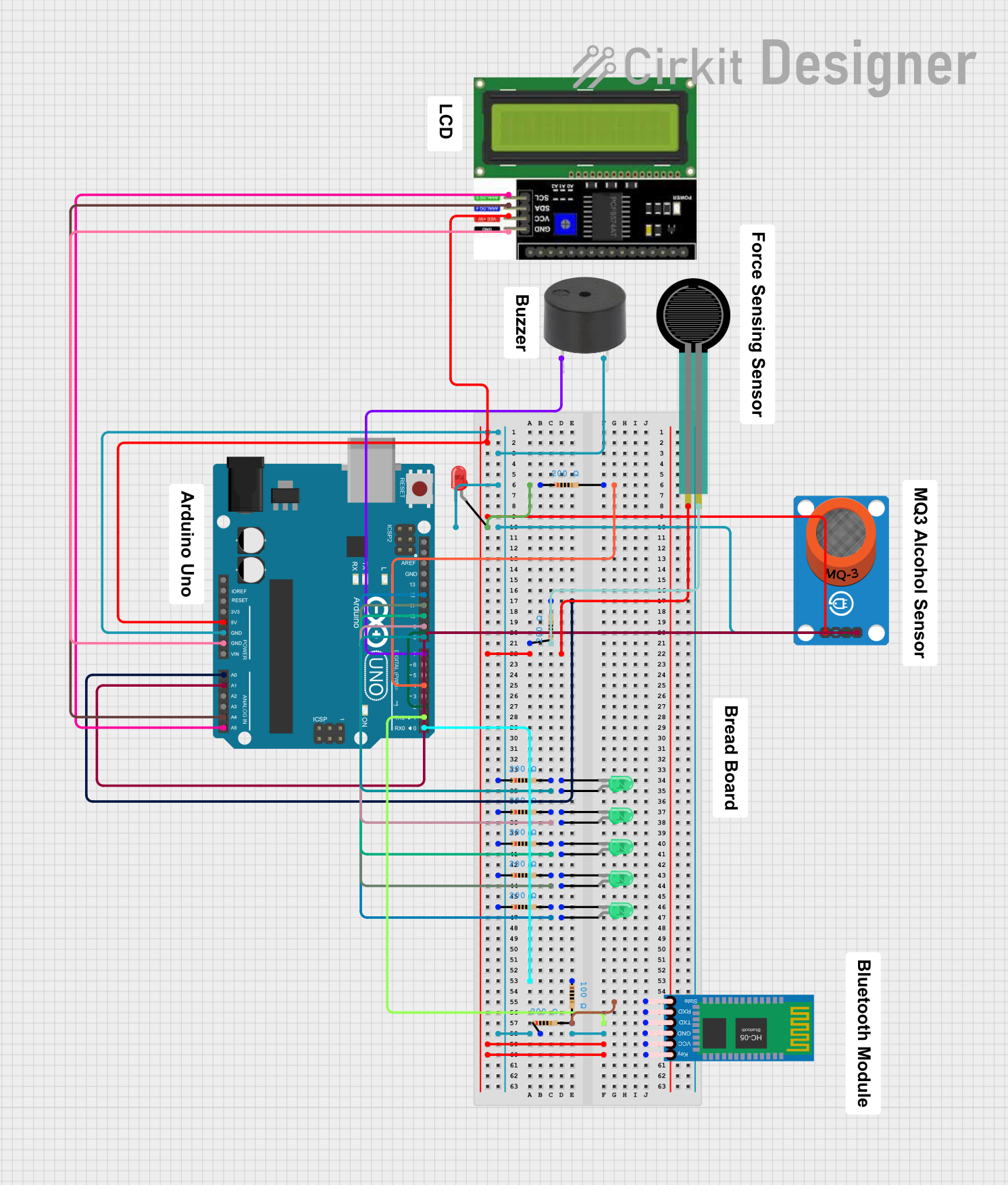
Circuit Documentation
Summary
This document provides a detailed overview of a circuit designed around an Arduino UNO microcontroller. The circuit includes various components such as LEDs, a buzzer, an LCD I2C display, a force sensing resistor, an MQ-3 alcohol sensor, and an HC-05 Bluetooth module. The circuit is designed to interface with these components, allowing for a range of functionalities such as visual feedback through LEDs, auditory signaling through a buzzer, data display on an LCD, and wireless communication via Bluetooth.
Component List
Arduino UNO
- Microcontroller board based on the ATmega328P
- It has 14 digital input/output pins, 6 analog inputs, a 16 MHz quartz crystal, a USB connection, a power jack, an ICSP header, and a reset button.
Buzzer
- An electromechanical component that produces sound
- Typically used for audible alerts or alarms.
LED: Two Pin (Red)
- A red light-emitting diode
- Used as an indicator light.
LED: Two Pin (Green)
- A green light-emitting diode
- Used as an indicator light.
LCD I2C Display
- A liquid crystal display with an I2C interface
- Used for displaying text and numbers.
Force Sensing Resistor
- A sensor that changes its resistance based on the force applied to its surface
- Used for sensing pressure or force.
MQ-3 Breakout
- An alcohol sensor module
- Used for detecting alcohol levels in the breath.
HC-05 Bluetooth Module
- A wireless communication module
- Used for Bluetooth connectivity with other devices.
Resistor (200 Ohms)
- A passive two-terminal electrical component
- Used to limit current or divide voltages.
Resistor (100 Ohms)
- Similar to the 200 Ohms resistor but with a lower resistance value.
Wiring Details
Arduino UNO
- Digital Pin D4 connected to Red LED anode through a 200 Ohms resistor
- Analog Pin A0 connected to one end of a 200 Ohms resistor, the other end connected to a Force Sensing Resistor
- Digital Pins D8, D9, D10, D11, D12 connected to Green LEDs anodes through 200 Ohms resistors
- Digital Pin D0 connected to one end of a 100 Ohms resistor
- Digital Pin D1 connected to TXD of HC-05 Bluetooth Module
- Digital Pin D2 connected to DO of MQ-3 Breakout
- Digital Pin D7 connected to Buzzer PIN
- Analog Pin A1 connected to AO of MQ-3 Breakout
- Analog Pins A4, A5 connected to SDA, SCL of LCD I2C Display respectively
- 5V and GND pins provide power to various components
Buzzer
- PIN connected to Digital Pin D7 of Arduino UNO
- GND connected to common ground
Red LED
- Anode connected to Digital Pin D4 of Arduino UNO through a 200 Ohms resistor
- Cathode connected to common ground
Green LEDs
- Anodes connected to Digital Pins D8, D9, D10, D11, D12 of Arduino UNO through 200 Ohms resistors
- Cathodes connected to common ground
LCD I2C Display
- VCC connected to 5V of Arduino UNO
- GND connected to common ground
- SDA connected to Analog Pin A4 of Arduino UNO
- SCL connected to Analog Pin A5 of Arduino UNO
Force Sensing Resistor
- One end connected to Analog Pin A0 of Arduino UNO through a 200 Ohms resistor
- The other end left unconnected (floating)
MQ-3 Breakout
- VCC connected to 5V of Arduino UNO
- GND connected to common ground
- DO connected to Digital Pin D2 of Arduino UNO
- AO connected to Analog Pin A1 of Arduino UNO
HC-05 Bluetooth Module
- VCC connected to 5V of Arduino UNO
- GND connected to common ground
- TXD connected to Digital Pin D1 of Arduino UNO
- State connected to one end of a 100 Ohms resistor, the other end connected to a 200 Ohms resistor and common ground
Resistor (200 Ohms)
- Used in series with LEDs and for pull-down configurations
Resistor (100 Ohms)
- Used in series with the State pin of HC-05 Bluetooth Module
Documented Code
Arduino UNO Code (sketch.ino)
void setup() {
  // put your setup code here, to run once:

}

void loop() {
  // put your main code here, to run repeatedly:

}
Note: The provided code is a template and does not include any functionality. It needs to be populated with the logic to control the components based on the requirements of the circuit's application.