
ESP32-Based Water Quality Monitoring and Automatic Solenoid Valve Control System
View and Edit Project In Cirkit Designer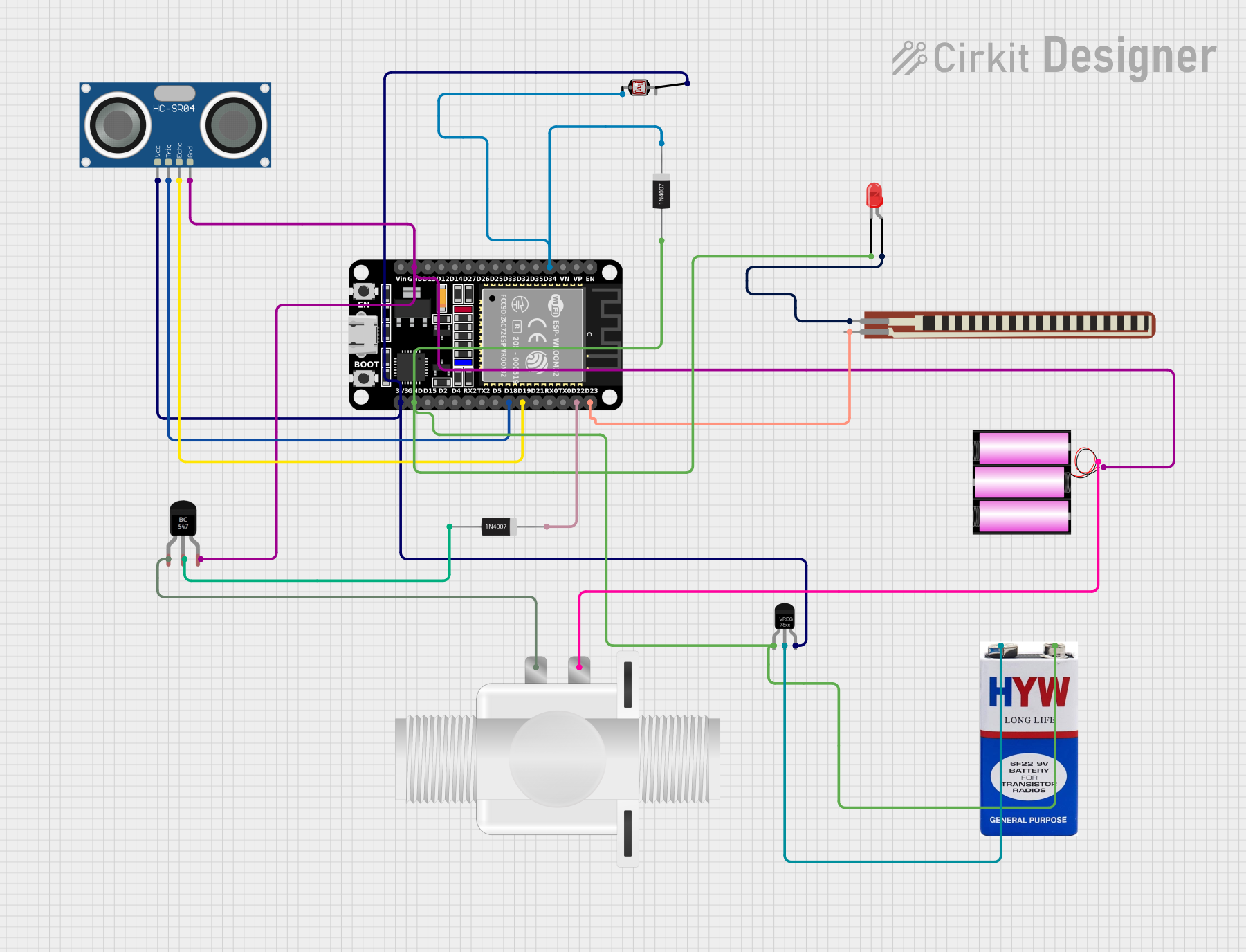
Circuit Documentation
Summary
This circuit integrates various components controlled by an ESP32 microcontroller to monitor water level and quality, and to actuate a solenoid valve based on the quality of the water. The system uses an HC-SR04 Ultrasonic Sensor to measure water level, a Photocell (LDR) to assess water quality, and a BC547 Transistor to control a Plastic Solenoid Valve. An LED indicates the water quality status. The ESP32 microcontroller is programmed to send the water level and quality data to a Firebase database and to control the LED and solenoid valve based on the water quality readings.
Component List
ESP32 (30 pin)
- A microcontroller with WiFi capabilities, used as the central processing unit of the circuit.
HC-SR04 Ultrasonic Sensor
- A sensor that measures distance using ultrasonic waves, used to determine the water level.
LED: Two Pin (red)
- A red LED used as an indicator for water quality.
2.2 inch Basic Flex Resistor
- A flexible resistor, possibly used as a sensor or for protection in the circuit.
Photocell (LDR)
- A light-dependent resistor used to measure water quality based on turbidity or color.
BC547 Transistor
- A general-purpose NPN transistor used to control the solenoid valve.
Plastic Solenoid Valve
- An electrically-controlled valve used to control the flow of water.
1N4007 Rectifier Diode (x2)
- Diodes used for protecting the circuit from reverse voltage spikes.
Battery 12V
- A 12V battery used as the power source for the solenoid valve.
Voltage Regulator
- A component that regulates the input voltage to a steady output voltage, used to power the ESP32 and sensors.
9V Battery
- A 9V battery used as the power source for the voltage regulator.
Wiring Details
ESP32 (30 pin)
D34connected to Photocell (LDR) and 1N4007 Rectifier Diode (Cathode)GNDconnected to 12V Battery (-), HC-SR04 Ultrasonic Sensor (GND), BC547 Transistor (Emitter), Voltage Regulator (GND), LED (Cathode), 9V Battery (-)D23connected to 2.2 inch Basic Flex Resistor (pin 1)D22connected to 1N4007 Rectifier Diode (Cathode)D19connected to HC-SR04 Ultrasonic Sensor (ECHO)D18connected to HC-SR04 Ultrasonic Sensor (TRIG)3V3connected to Voltage Regulator (OUT), Photocell (LDR), HC-SR04 Ultrasonic Sensor (VCC)
HC-SR04 Ultrasonic Sensor
VCCconnected to ESP32 (3V3)TRIGconnected to ESP32 (D18)ECHOconnected to ESP32 (D19)GNDconnected to ESP32 (GND)
LED: Two Pin (red)
cathodeconnected to ESP32 (GND)anodeconnected to 2.2 inch Basic Flex Resistor (Pin 2)
2.2 inch Basic Flex Resistor
Pin 2connected to LED (anode)pin 1connected to ESP32 (D23)
Photocell (LDR)
pin 0connected to ESP32 (D34), 1N4007 Rectifier Diode (Cathode)pin 1connected to ESP32 (3V3)
BC547 Transistor
Collectorconnected to Plastic Solenoid Valve (pin2)Baseconnected to 1N4007 Rectifier Diode (Anode)Emitterconnected to ESP32 (GND)
Plastic Solenoid Valve
pin1connected to 12V Battery (+)pin2connected to BC547 Transistor (Collector)
1N4007 Rectifier Diode
Cathodeconnected to ESP32 (D34), Photocell (LDR)Anodeconnected to BC547 Transistor (Base)
Battery 12V
+connected to Plastic Solenoid Valve (pin1)-connected to ESP32 (GND)
Voltage Regulator
GNDconnected to ESP32 (GND)INconnected to 9V Battery (+)OUTconnected to ESP32 (3V3)
9V Battery
+connected to Voltage Regulator (IN)-connected to ESP32 (GND)
Documented Code
#include <FirebaseESP32.h>
#include <WiFi.h>

// Firebase config and credentials
#define FIREBASE_HOST "your-firebase-project-id.firebaseio.com"
#define FIREBASE_AUTH "your-firebase-auth-key"

// WiFi credentials
#define WIFI_SSID "your-ssid"
#define WIFI_PASSWORD "your-password"

// Pins for Ultrasonic sensor
#define TRIG_PIN 18
#define ECHO_PIN 19

// Pin for Water Quality sensor (Photocell)
#define PHOTO_PIN 34

// Pin for LED
#define LED_PIN 23

// Pin for Solenoid Valve (BC547 transistor control)
#define VALVE_PIN 19

// Firebase data object
FirebaseData firebaseData;

// Variables for water level and quality
long duration;
int distance;
int qualityValue;

void setup() {
  Serial.begin(115200);

  // Initialize pins
  pinMode(TRIG_PIN, OUTPUT);
  pinMode(ECHO_PIN, INPUT);
  pinMode(PHOTO_PIN, INPUT);
  pinMode(LED_PIN, OUTPUT);
  pinMode(VALVE_PIN, OUTPUT);

  // Initialize WiFi
  WiFi.begin(WIFI_SSID, WIFI_PASSWORD);
  while (WiFi.status() != WL_CONNECTED) {
    delay(1000);
    Serial.println("Connecting to WiFi...");
  }
  Serial.println("Connected to WiFi");

  // Firebase initialization
  Firebase.begin(FIREBASE_HOST, FIREBASE_AUTH);
  Firebase.reconnectWiFi(true);

  Serial.println("Firebase initialized");
}

void loop() {
  // Read Water Level (Ultrasonic Sensor)
  digitalWrite(TRIG_PIN, LOW);
  delayMicroseconds(2);
  digitalWrite(TRIG_PIN, HIGH);
  delayMicroseconds(10);
  digitalWrite(TRIG_PIN, LOW);

  duration = pulseIn(ECHO_PIN, HIGH);
  distance = duration * 0.034 / 2; // Calculate distance in cm

  // Read Water Quality (Photocell Sensor)
  qualityValue = analogRead(PHOTO_PIN);

  // Control LED based on water quality
  if (qualityValue < 500) {
    digitalWrite(LED_PIN, HIGH); // Bad quality (turn on LED)
  } else {
    digitalWrite(LED_PIN, LOW);  // Good quality (turn off LED)
  }

  // Update data to Firebase
  Firebase.setInt(firebaseData, "/water_level", distance);
  Firebase.setInt(firebaseData, "/water_quality", qualityValue);

  // Control Solenoid Valve automatically (if low water quality)
  if (qualityValue < 500) {
    digitalWrite(VALVE_PIN, HIGH); // Open valve
  } else {
    digitalWrite(VALVE_PIN, LOW);  // Close valve
  }

  // Print the values
  Serial.print("Water Level: ");
  Serial.print(distance);
  Serial.println(" cm");

  Serial.print("Water Quality: ");
  Serial.println(qualityValue);

  delay(2000); // Delay before next reading
}
This code is designed to run on the ESP32 microcontroller. It initializes the necessary pins, connects to WiFi, and sets up Firebase for data logging. The loop function reads the water level using the ultrasonic sensor, measures water quality with the photocell, and controls the LED and solenoid valve based on the quality of the water. It also sends the data to Firebase for remote monitoring.