
Arduino Mega 2560 and ESP32-Based Smart Smoke and Gas Detection System with Solar Power
View and Edit Project In Cirkit Designer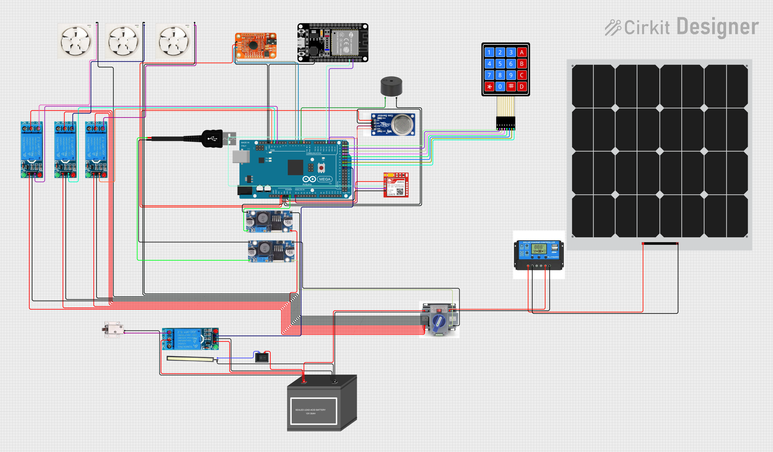
Circuit Documentation
Summary
This circuit is designed for an automatic system that opens a solenoid lock and activates a buzzer when the MQ2 sensor detects smoke or gas. The system also includes a DFPlayer Mini for audio output, a voice recognition module, and an ESP32 for additional functionalities. The circuit is powered by a 12V battery and a solar panel with a charge controller.
Component List
12V Battery (mini)
- Pins: -, +
- Description: Provides 12V power to the circuit.
MQ2
- Pins: D0, A0, GND, VCC
- Description: Gas and smoke sensor.
Voice recognition module
- Pins: GND, VCC, RDX, RTX
- Description: Module for voice command recognition.
Exhaust Fan 12"
- Pins: Live, Neutral
- Description: 12-inch exhaust fan.
Solar Panel
- Pins: +, -
- Description: Converts solar energy to electrical energy.
ATS
- Pins: +, -
- Description: Automatic Transfer Switch.
12V solenoid lock
- Pins: VCC, GND
- Description: Electromagnetic lock.
Step down Buck converter
- Pins: IN +, IN - GND, OUT +, OUT - GND
- Description: Converts higher voltage to a lower voltage.
ESP32 (30 pin)
- Pins: EN, VP, VN, D34, D35, D32, D33, D25, D26, D27, D14, D12, D13, GND, Vin, D23, D22, TX0, RX0, D21, D19, D18, D5, TX2, RX2, D4, D2, D15, 3V3
- Description: Microcontroller with Wi-Fi and Bluetooth capabilities.
12V SINGLE CHANNEL RELAY
- Pins: NC, COM, NO, IN, GND, VCC
- Description: Relay module for switching.
Charge Controller
- Pins: Solar Positive, Solar Negative, Battery Positive, Battery Negative, Load Positive, Load Negative
- Description: Manages the charging of the battery from the solar panel.
4X4 Membrane Matrix Keypad
- Pins: R1, R2, R3, R4, C1, C2, C3, C4
- Description: Keypad for user input.
USB male 2 pin connection
- Pins: Negative -, Positive +
- Description: USB connection for power or data.
Buzzer
- Pins: PIN, GND
- Description: Audio alert device.
LED 12V
- Pins: POSITIF, NEGATIF
- Description: 12V LED indicator.
Rocker Switch (SPST)
- Pins: 1, 2
- Description: Single Pole Single Throw switch.
Sim800l
- Pins: NET, RST, VCC, RXD, TXD, GND
- Description: GSM/GPRS module.
Arduino Mega 2560
- Pins: IOREF, RESET, 3V3, 5V, GND, VIN, A0, A1, A2, A3, A4, A5, A6, A7, A8, A9, A10, A11, A12, A13, A14, A15, D21/SCL, D20/SDA, D19/RX1, D18/TX1, D17 PWM/RX2, D16 PWM/TX2, D15/RX3, D14/TX3, D0 RX0, D1 TX0, D2 PWM, D3 PWM, D4 PWM, D5 PWM, D6 PWM, D7 PWM, D8 PWM, D9 PWM, D10 PWM, D11 PWM, D12 PWM, D13 PWM, AREF, SDA, SCL, D52, D50, D48, D46, D44, D42, D40, D38, D36, D34, D32, D30, D28, D26, D24, D22, D53, D51, D49, D47, D45, D43, D41, D39, D37, D35, D33, D31, D29, D27, D25, D23
- Description: Microcontroller board based on the ATmega2560.
Wiring Details
12V Battery (mini)
- -: Connected to ATS (-), 12V solenoid lock (GND), 12V SINGLE CHANNEL RELAY (GND), led 12v (POSITIF)
- +: Connected to ATS (+), Rocker Switch (SPST) (2), 12V SINGLE CHANNEL RELAY (COM), 12V SINGLE CHANNEL RELAY (VCC)
MQ2
- D0: Connected to Arduino Mega 2560 (D2 PWM)
- A0: Connected to Arduino Mega 2560 (A0)
- GND: Connected to Step down Buck converter (OUT - GND), buzzer (GND), Arduino Mega 2560 (GND)
- VCC: Connected to Voice recognition module (VCC), Sim800l (VCC), Arduino Mega 2560 (5V)
Voice recognition module
- GND: Connected to ESP32 (30 pin) (GND), Arduino Mega 2560 (GND)
- VCC: Connected to MQ2 (VCC), Sim800l (VCC), Arduino Mega 2560 (5V)
- RDX: Connected to Arduino Mega 2560 (D4 PWM)
- RTX: Connected to Arduino Mega 2560 (D5 PWM)
Exhaust Fan 12"
- Live: Connected to 12V SINGLE CHANNEL RELAY (NO)
- Neutral: Connected to 12V SINGLE CHANNEL RELAY (GND), Step down Buck converter (IN - GND), ATS (-), Exhaust Fan 12" (Neutral), Exhaust Fan 12" (Neutral), 12V SINGLE CHANNEL RELAY (GND), 12V SINGLE CHANNEL RELAY (GND)
Solar Panel
- +: Connected to Charge Controller (Solar Positive)
- -: Connected to Charge Controller (Solar Negative)
ATS
- +: Connected to Rocker Switch (SPST) (2), 12V SINGLE CHANNEL RELAY (COM), 12V SINGLE CHANNEL RELAY (VCC), 12V Battery (mini) (+), Step down Buck converter (IN +), Charge Controller (Load Positive)
- -: Connected to 12V solenoid lock (GND), 12V SINGLE CHANNEL RELAY (GND), 12V Battery (mini) (-), Step down Buck converter (IN - GND), Charge Controller (Load Negative)
12V solenoid lock
- VCC: Connected to 12V SINGLE CHANNEL RELAY (NO)
- GND: Connected to ATS (-), 12V SINGLE CHANNEL RELAY (GND), 12V Battery (mini) (-), led 12v (POSITIF)
Step down Buck converter
- IN +: Connected to ATS (+)
- IN - GND: Connected to ATS (-)
- OUT +: Connected to Arduino Mega 2560 (VIN), USB male 2 pin connection (Positive +)
- OUT - GND: Connected to MQ2 (GND), buzzer (GND), Arduino Mega 2560 (GND), USB male 2 pin connection (Negative -)
ESP32 (30 pin)
- TX0: Connected to Sim800l (TXD), Arduino Mega 2560 (D19/RX1)
- RX0: Connected to Sim800l (RXD), Arduino Mega 2560 (D18/TX1)
- GND: Connected to Voice recognition module (GND), Arduino Mega 2560 (GND)
12V SINGLE CHANNEL RELAY
- NC: Not connected
- COM: Connected to ATS (+), 12V Battery (mini) (+)
- NO: Connected to 12V solenoid lock (VCC), Exhaust Fan 12" (Live)
- IN: Connected to Arduino Mega 2560 (D11 PWM), Arduino Mega 2560 (D12 PWM), Arduino Mega 2560 (D13 PWM), Arduino Mega 2560 (D38)
- GND: Connected to ATS (-), 12V solenoid lock (GND), 12V Battery (mini) (-), Step down Buck converter (IN - GND), Exhaust Fan 12" (Neutral), Exhaust Fan 12" (Neutral), 12V SINGLE CHANNEL RELAY (G