Arduino-Controlled IR Relay Switching System
Circuit Documentation
Summary of the Circuit
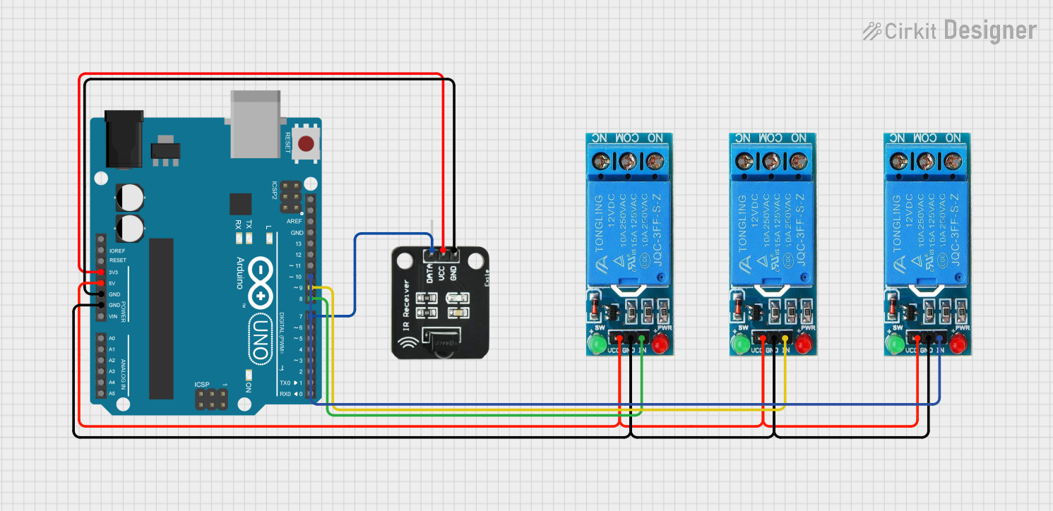
This circuit is designed to interface an Arduino UNO with multiple 12V single-channel relays and an IR receiver. The Arduino UNO controls the relays through its digital output pins and receives data from the IR receiver through one of its digital input pins. The relays are used to switch higher voltage loads, which are not specified in the provided information. The IR receiver is used to receive infrared signals, which could be from a remote control or another IR transmitter. The circuit is powered by the Arduino UNO's onboard voltage regulators, with the relays receiving 5V and the IR receiver receiving 3.3V.
Component List
Arduino UNO
- Description: A microcontroller board based on the ATmega328P.
- Pins: UNUSED, IOREF, Reset, 3.3V, 5V, GND, Vin, A0-A5, SCL, SDA, AREF, D0-D13.
12V Single Channel Relay (x3)
- Description: An electromechanical switch that allows a low-power signal to control a higher power circuit.
- Pins: NC (Normally Closed), COM (Common), NO (Normally Open), IN (Input), GND (Ground), VCC (Voltage Supply).
IR Receiver
- Description: A component that receives infrared signals and outputs the signal as an electrical pulse.
- Pins: DATA, VCC, GND.
Wiring Details
Arduino UNO
- Digital Pin D9: Connected to Relay 1 IN pin.
- Digital Pin D10: Connected to Relay 2 IN pin.
- Digital Pin D8: Connected to Relay 3 IN pin.
- Digital Pin D7: Connected to IR Receiver DATA pin.
- Pin 5V: Connected to VCC pins of all Relays.
- Pin 3.3V: Connected to IR Receiver VCC pin.
- Pin GND: Connected to GND pins of all Relays and IR Receiver.
12V Single Channel Relay 1
- IN: Controlled by Arduino UNO Digital Pin D9.
- VCC: Powered by Arduino UNO 5V pin.
- GND: Connected to Arduino UNO GND.
12V Single Channel Relay 2
- IN: Controlled by Arduino UNO Digital Pin D10.
- VCC: Powered by Arduino UNO 5V pin.
- GND: Connected to Arduino UNO GND.
12V Single Channel Relay 3
- IN: Controlled by Arduino UNO Digital Pin D8.
- VCC: Powered by Arduino UNO 5V pin.
- GND: Connected to Arduino UNO GND.
IR Receiver
- DATA: Connected to Arduino UNO Digital Pin D7.
- VCC: Powered by Arduino UNO 3.3V pin.
- GND: Connected to Arduino UNO GND.
Documented Code
Arduino UNO Code (sketch.ino)
void setup() {
  // put your setup code here, to run once:

}

void loop() {
  // put your main code here, to run repeatedly:

}
Note: The provided code is a template and does not contain any functional code to control the relays or read data from the IR receiver. The user is expected to fill in the setup and loop functions with the necessary code to implement the desired functionality.