Cirkit Designer
Your all-in-one circuit design IDE
Home /
Project Documentation
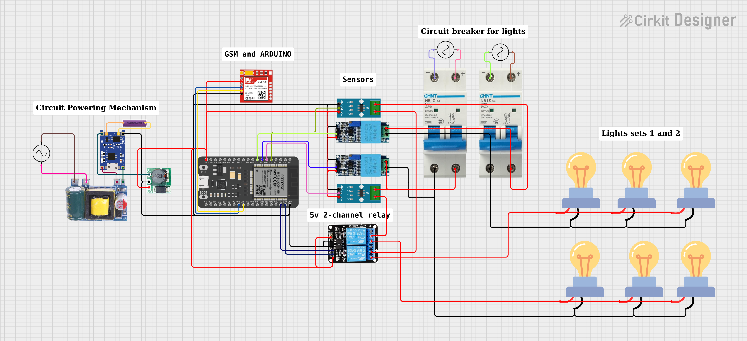
ESP32-Based Power Monitoring and SMS Control System
Circuit Documentation
Summary
The circuit is designed to monitor voltage and current, calculate power, and control lighting systems. It includes current sensors, voltage sensors, LED bulbs, a microcontroller (ESP32), a GSM module for communication, relays for controlling the lights, a battery charging module, and power supplies. The ESP32 microcontroller is programmed to read sensor data, calculate power, and send notifications via the GSM module based on predefined conditions. It also responds to SMS commands to control the lights through the relay module.
Component List
ACS712 Current Sensor 5A 20A 30A
- Description: A current sensor module based on the ACS712 sensor, capable of measuring current in the range of 5A, 20A, or 30A.
- Pins: 1, 2, GND, OUT, VCC
Voltage Sensor
- Description: A module for measuring voltage in a circuit.
- Pins: Ground, Phase, Vcc, Out, Gnd
LED bulb AC / Bombillo AC
- Description: An LED bulb designed for AC power.
- Pins: +, -
Ac Supply
- Description: A power supply module providing AC voltage.
- Pins: +ve, -ve
Circuit Breaker
- Description: A safety device designed to protect an electrical circuit from damage caused by excess current.
- Pins: -, +
5v 2-Relay JD-VCC
- Description: A 5V 2-channel relay module used for switching high power devices.
- Pins: JD-VCC, VCC, GND, IN1, IN2, NO, COM, NC
Mini AC-DC 110V-230V to 5V 700mA Module
- Description: A power supply module that converts AC voltage to 5V DC.
- Pins: GND, 5v, Neutral, Life
TP4056
- Description: A lithium battery charging module.
- Pins: OUT-, B-, B+, OUT+, IN-, IN+
Step Up Boost 3v- 5v
- Description: A DC-DC step-up converter module that boosts voltage from 3V to 5V.
- Pins: Vi, GND, Vo
3.7v battery
- Description: A rechargeable lithium battery rated at 3.7V.
- Pins: +, -
ESP32 - 38 pins
- Description: A microcontroller with Wi-Fi and Bluetooth capabilities.
- Pins: Various GPIOs, power, and ground pins.
Sim800l
- Description: A GSM/GPRS module for cellular communication.
- Pins: NET, RST, VCC, RXD, TXD, GND
Wiring Details
ACS712 Current Sensor
- 1, 2: Connected to the relay COM pin and the circuit breaker + pin respectively.
- GND: Common ground with other components.
- OUT: Connected to ESP32 GPIOs for current sensing.
- VCC: Powered by 5V from the relay VCC pin.
Voltage Sensor
- Ground, Gnd: Common ground with other components.
- Phase: Connected to the circuit breaker + pin.
- Vcc: Powered by 5V from the relay VCC pin.
- Out: Connected to ESP32 GPIOs for voltage sensing.
LED bulb AC / Bombillo AC
- +: Connected to the relay NO pin.
- -: Connected to the circuit breaker - pin.
Ac Supply
- +ve: Connected to the Mini AC-DC module Life pin and the circuit breaker + pin.
- -ve: Connected to the Mini AC-DC module Neutral pin and the circuit breaker - pin.
Circuit Breaker
- +: Connected to the voltage sensor Phase pin and the relay COM pin.
- -: Connected to the LED bulb - pin.
5v 2-Relay JD-VCC
- JD-VCC: Independent relay power supply.
- VCC: Powered by 5V from the Mini AC-DC module.
- GND: Common ground with other components.
- IN1, IN2: Controlled by ESP32 GPIOs.
- NO: Connected to the LED bulb + pin.
- COM: Connected to the circuit breaker + pin.
Mini AC-DC 110V-230V to 5V 700mA Module
- GND: Common ground with other components.
- 5v: Provides 5V power to the TP4056 module and the relay VCC pin.
- Neutral: Connected to the Ac Supply -ve pin.
- Life: Connected to the Ac Supply +ve pin.
TP4056
- OUT-, IN-: Connected to the battery - pin and the Mini AC-DC GND pin respectively.
- B-, B+: Connected to the battery - and + pins respectively.
- OUT+, IN+: Connected to the battery + pin and the Mini AC-DC 5v pin respectively.
Step Up Boost 3v- 5v
- Vi: Connected to the TP4056 OUT+ pin.
- GND: Common ground with other components.
- Vo: Provides 5V power to the ESP32 5V pin.
3.7v battery
- +: Connected to the TP4056 B+ and OUT+ pins.
- -: Connected to the TP4056 B- and OUT- pins.
ESP32 - 38 pins
- GND: Common ground with other components.
- 5V: Powered by 5V from the Step Up Boost Vo pin.
- GPIOs: Connected to various components for control and sensing.
Sim800l
- GND: Common ground with other components.
- VCC: Powered by 5V from the relay VCC pin.
- RXD, TXD: Connected to ESP32 GPIOs for serial communication.
Documented Code
ESP32 - Power Monitor Code
/*
 * This Arduino Sketch is for an ESP32 microcontroller connected to two sets of
 * voltage and current sensors, a GSM 800L module, and a 5V 2-channel relay.
 * The code reads voltage and current values, calculates power, and sends
 * notifications via GSM based on predefined conditions. It also controls
 * two sets of lights via the relay module based on received SMS commands.
 */

#include <SoftwareSerial.h>

// Pin definitions
#define VOLTAGE_SENSOR_1_PIN 33
#define CURRENT_SENSOR_1_PIN 34
#define VOLTAGE_SENSOR_2_PIN 32
#define CURRENT_SENSOR_2_PIN 35
#define RELAY_IN1_PIN 22
#define RELAY_IN2_PIN 23
#define GSM_TX_PIN 17
#define GSM_RX_PIN 16

// Predefined power thresholds
const float power_calc_1 = 1000.0; // 1000W for set 1
const float power_calc_2 = 1000.0; // 1000W for set 2

// Variables to store sensor readings
float voltage1 = 0.0;
float current1 = 0.0;
float power1 = 0.0;
float voltage2 = 0.0;
float current2 = 0.0;
float power2 = 0.0;

// GSM module setup
SoftwareSerial gsm(GSM_RX_PIN, GSM_TX_PIN);

void setup() {
  Serial.begin(115200);
  gsm.begin(9600);

  pinMode(RELAY_IN1_PIN, OUTPUT);
  pinMode(RELAY_IN2_PIN, OUTPUT);

  digitalWrite(RELAY_IN1_PIN, LOW);
  digitalWrite(RELAY_IN2_PIN, LOW);
}

void loop() {
  // Read sensors and calculate power
  voltage1 = analogRead(VOLTAGE_SENSOR_1_PIN) * (5.0 / 1023.0);
  current1 = analogRead(CURRENT_SENSOR_1_PIN) * (5.0 / 1023.0);
  power1 = voltage1 * current1;

  voltage2 = analogRead(VOLTAGE_SENSOR_2_PIN) * (5.0 / 1023.0);
  current2 = analogRead(CURRENT_SENSOR_2_PIN) * (5.0 / 1023.0);
  power2 = voltage2 * current2;

  // Check for incoming SMS
  if (gsm.available()) {
    String message = gsm.readString();
    if (message.indexOf("Status") >= 0) {
      sendStatus();
    } else if (message.indexOf("Light 1") >= 0) {
      digitalWrite(RELAY_IN1_PIN, HIGH);
    } else if (message.indexOf("Light 2") >= 0) {
      digitalWrite(RELAY_IN2_PIN, HIGH);
    }
  }

  // Check power thresholds and send notifications
  if (power1 < power_calc_1) {
    sendNotification("Power 1 below threshold");
  }
  if (power2 < power_calc_2) {
    sendNotification("Power 2 below threshold");
  }

  delay(1000); // Delay for 1 second
}

void sendStatus() {
  gsm.print("AT+CMGF=1\r");
  delay(100);
  gsm.print("AT+CMGS=\"+237671693917\"\r");
  delay(100);
  gsm.print("Voltage 1: ");
  gsm.print(voltage1);
  gsm.print("V, Current 1: ");
  gsm.print(current1);
  gsm.print("A, Power 1: ");
  gsm.print(power1);