
Arduino Mega 2560 Based Health Monitoring Station with TFT Display and Environmental Sensing
View and Edit Project In Cirkit Designer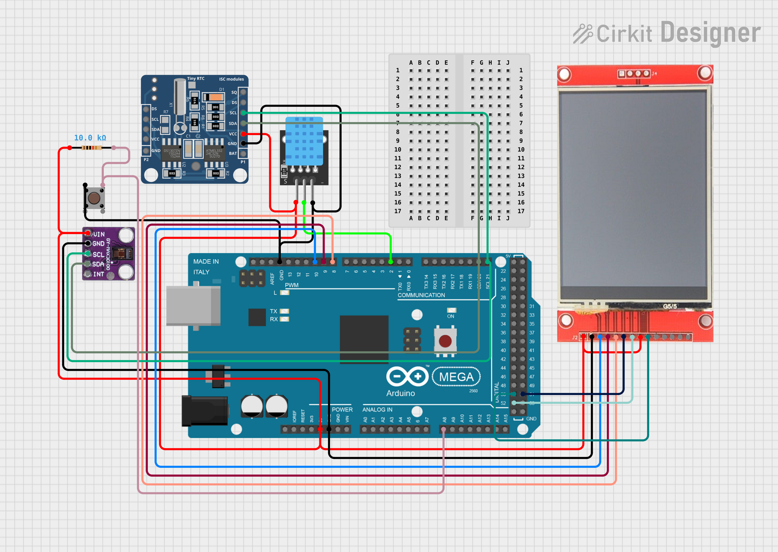
Circuit Documentation
Summary
This circuit is designed to interface an Arduino Mega 2560 with several peripherals including an ili9341 TFT display, a KY-015 DHT11 temperature and humidity sensor, a DS1307 real-time clock (RTC), a MAX30100 pulse oximeter, and a pushbutton with a pull-up resistor. The Arduino Mega 2560 serves as the central microcontroller unit, managing data acquisition from the sensors, controlling the display output, and responding to user input via the pushbutton. The circuit is powered by the 5V output from the Arduino and includes necessary connections for I2C communication and digital signal interfacing.
Component List
ili9341 TFT Display
- Description: A color graphic display for visual output.
- Pins: VCC, GND, CS, RESET, DC/RS, SDI, SCK, LED, SDO, T_CLK, T_CS, T_DIN, T_DO, T_IRQ
KY-015 DHT11
- Description: A sensor for measuring temperature and humidity.
- Pins: 5V, S, GND
Arduino Mega 2560
- Description: A microcontroller board based on the ATmega2560.
- Pins: Multiple digital and analog pins, including IOREF, RESET, 3V3, 5V, GND, VIN, A0-A15, D0-D53, AREF, SDA, SCL
RTC DS1307
- Description: A real-time clock for keeping track of the current time and date.
- Pins: DS, SCL, SDA, VCC, GND, BAT, SQ
MAX30100
- Description: A pulse oximeter and heart-rate sensor.
- Pins: Vin, gnd, scl, sda, int
Pushbutton
- Description: A momentary pushbutton switch for user input.
- Pins: Pin 3 (out), Pin 4 (out), Pin 1 (in), Pin 2 (in)
Resistor (10k Ohms)
- Description: A resistor used for pull-up configuration on the pushbutton.
- Pins: pin1, pin2
- Value: 10,000 Ohms
Wiring Details
ili9341 TFT Display
- VCC: Connected to 5V from Arduino Mega 2560
- GND: Connected to GND on Arduino Mega 2560
- CS: Connected to digital pin 10 (D10 PWM) on Arduino Mega 2560
- RESET: Connected to digital pin 9 (D9 PWM) on Arduino Mega 2560
- DC/RS: Connected to digital pin 8 (D8 PWM) on Arduino Mega 2560
- SDI: Connected to digital pin 51 (D51) on Arduino Mega 2560
- SCK: Connected to digital pin 52 (D52) on Arduino Mega 2560
- LED: Connected to 5V from Arduino Mega 2560
- SDO: Connected to digital pin 50 (D50) on Arduino Mega 2560
KY-015 DHT11
- 5V: Connected to 5V from Arduino Mega 2560
- S: Connected to digital pin 2 (D2 PWM) on Arduino Mega 2560
- GND: Connected to GND on Arduino Mega 2560
RTC DS1307
- VCC: Connected to 5V from Arduino Mega 2560
- SCL: Connected to digital pin 21 (D21/SCL) on Arduino Mega 2560
- SDA: Connected to digital pin 20 (D20/SDA) on Arduino Mega 2560
- GND: Connected to GND on Arduino Mega 2560
MAX30100
- Vin: Connected to 5V from Arduino Mega 2560
- gnd: Connected to GND on Arduino Mega 2560
- scl: Connected to digital pin 21 (D21/SCL) on Arduino Mega 2560
- sda: Connected to digital pin 20 (D20/SDA) on Arduino Mega 2560
Pushbutton
- Pin 1 (in): Connected to GND on Arduino Mega 2560
- Pin 3 (out): Connected to analog pin 8 (A8) on Arduino Mega 2560 through a 10k Ohm resistor
Resistor (10k Ohms)
- pin1: Connected to 5V from Arduino Mega 2560
- pin2: Connected to analog pin 8 (A8) on Arduino Mega 2560 and Pin 3 (out) on Pushbutton
Documented Code
#include <Wire.h>
#include <Adafruit_GFX.h>
#include <Adafruit_ILI9341.h>
#include <RTClib.h>
#include <DHT.h>
#include <MAX30100_PulseOximeter.h>

// Pin definitions
#define TFT_CS     10
#define TFT_RST    9
#define TFT_DC     8
#define DHT_PIN    2
#define BUTTON_PIN A8

// Create instances for the components
Adafruit_ILI9341 tft = Adafruit_ILI9341(TFT_CS, TFT_DC, TFT_RST);
RTC_DS1307 rtc;
DHT dht(DHT_PIN, DHT11);
PulseOximeter pox;

// Variables to store sensor data
float temperature, humidity;
uint8_t heartRate;
float spo2;
bool displayHeartRate = false;

void setup() {
  // Initialize serial communication
  Serial.begin(9600);

  // Initialize the display
  tft.begin();
  tft.setRotation(3);
  tft.fillScreen(ILI9341_BLACK);
  tft.setTextColor(ILI9341_WHITE);
  tft.setTextSize(2);

  // Initialize the RTC
  if (!rtc.begin()) {
    Serial.println("Couldn't find RTC");
    while (1);
  }
  if (!rtc.isrunning()) {
    Serial.println("RTC is NOT running!");
    rtc.adjust(DateTime(F(__DATE__), F(__TIME__)));
  }

  // Initialize the DHT sensor
  dht.begin();

  // Initialize the MAX30100 sensor
  if (!pox.begin()) {
    Serial.println("Failed to initialize pulse oximeter");
    while (1);
  }
  pox.setOnBeatDetectedCallback(onBeatDetected);

  // Initialize the pushbutton
  pinMode(BUTTON_PIN, INPUT_PULLUP);
}

void loop() {
  // Check if the button is pressed
  if (digitalRead(BUTTON_PIN) == LOW) {
    displayHeartRate = !displayHeartRate;
    delay(500); // Debounce delay
  }

  if (displayHeartRate) {
    // Read heart rate and SpO2
    pox.update();
    heartRate = pox.getHeartRate();
    spo2 = pox.getSpO2();

    // Display heart rate and SpO2
    tft.fillScreen(ILI9341_BLACK);
    tft.setCursor(0, 0);
    tft.print("Heart Rate: ");
    tft.print(heartRate);
    tft.println(" BPM");
    tft.print("SpO2: ");
    tft.print(spo2);
    tft.println(" %");
  } else {
    // Read temperature and humidity
    temperature = dht.readTemperature();
    humidity = dht.readHumidity();

    // Read time from RTC
    DateTime now = rtc.now();

    // Display time, temperature, and humidity
    tft.fillScreen(ILI9341_BLACK);
    tft.setCursor(0, 0);
    tft.print("Time: ");
    tft.print(now.hour());
    tft.print(":");
    tft.print(now.minute());
    tft.print(":");
    tft.println(now.second());
    tft.print("Temp: ");
    tft.print(temperature);
    tft.println(" C");
    tft.print("Humidity: ");
    tft.print(humidity);
    tft.println(" %");
  }

  delay(1000); // Update every second
}

void onBeatDetected() {
  Serial.println("Beat detected!");
}
This code initializes and manages the various components connected to the Arduino Mega 2560. It includes setup routines for the display, sensors, and RTC, as well as a loop that alternates between displaying heart rate and SpO2 data or temperature, humidity, and time based on the state of the pushbutton. The onBeatDetected callback function is used to indicate when a heartbeat is detected by the MAX30100 sensor.