
ESP8266 NodeMCU Controlled Ultrasonic Distance Measurement with LED Indicators
View and Edit Project In Cirkit Designer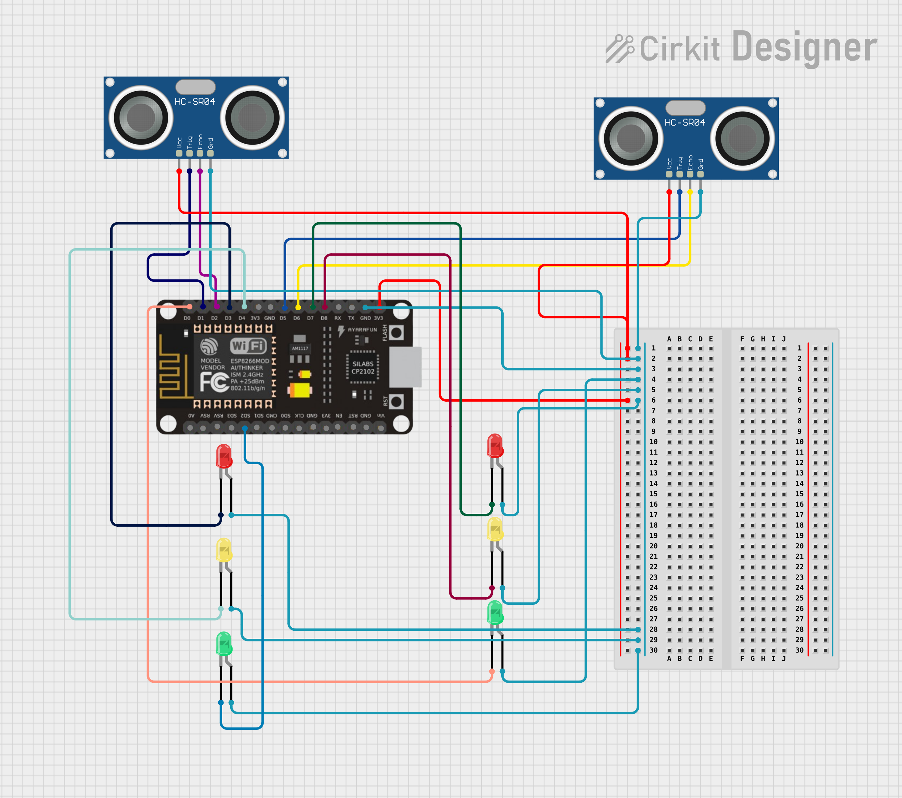
Circuit Documentation
Summary
The circuit in question is designed to interface an ESP8266 NodeMCU microcontroller with multiple LEDs and two HC-SR04 Ultrasonic Sensors. The ESP8266 NodeMCU controls the LEDs and triggers the ultrasonic sensors to measure distances. The LEDs are used as indicators, and their state is controlled by the digital pins of the ESP8266. The ultrasonic sensors are powered by the 3.3V output from the ESP8266 and are interfaced with specific GPIO pins for triggering and echo detection.
Component List
ESP8266 NodeMCU
- Description: A Wi-Fi capable microcontroller module with an ESP8266 chip.
- Pins: D0, D1, D2, D3, D4, 3V3, GND, D5, D6, D7, D8, RX, TX, A0, RSV, SD3, SD2, SD1, CMD, SD0, CLK, EN, RST, VIN
LED: Two Pin (red)
- Description: A standard red LED with an anode and cathode pin.
LED: Two Pin (green)
- Description: A standard green LED with an anode and cathode pin.
LED: Two Pin (yellow)
- Description: A standard yellow LED with an anode and cathode pin.
HC-SR04 Ultrasonic Sensor
- Description: An ultrasonic distance sensor with VCC, TRIG, ECHO, and GND pins.
Wiring Details
ESP8266 NodeMCU
- 3V3: Connected to VCC of both HC-SR04 Ultrasonic Sensors.
- GND: Connected to GND of both HC-SR04 Ultrasonic Sensors and anode pins of all LEDs.
- D0: Connected to the cathode of a green LED.
- D1: Connected to TRIG of the first HC-SR04 Ultrasonic Sensor.
- D2: Connected to ECHO of the first HC-SR04 Ultrasonic Sensor.
- D3: Connected to the cathode of a red LED.
- D4: Connected to the cathode of a yellow LED.
- D5: Connected to TRIG of the second HC-SR04 Ultrasonic Sensor.
- D6: Connected to ECHO of the second HC-SR04 Ultrasonic Sensor.
- D7: Connected to the cathode of another red LED.
- D8: Connected to the cathode of another yellow LED.
- SD2: Connected to the cathode of another green LED.
LEDs (red, green, yellow)
- Anode: Connected to GND of ESP8266 NodeMCU.
- Cathode: Connected to respective GPIO pins on the ESP8266 NodeMCU (D0, D3, D4, D7, D8, SD2).
HC-SR04 Ultrasonic Sensors
- VCC: Connected to 3V3 of ESP8266 NodeMCU.
- GND: Connected to GND of ESP8266 NodeMCU.
- TRIG: Connected to GPIO pins D1 and D5 of ESP8266 NodeMCU (for the first and second sensor respectively).
- ECHO: Connected to GPIO pins D2 and D6 of ESP8266 NodeMCU (for the first and second sensor respectively).
Documented Code
No code has been provided for the microcontroller. The expected code should initialize the GPIO pins connected to the LEDs as outputs and the pins connected to the TRIG and ECHO of the HC-SR04 sensors appropriately. The code should handle the triggering of the ultrasonic sensors and read the echo to calculate the distance. Based on the distance measured, the code should control the state of the LEDs (e.g., turn on a red LED if an object is too close).
Please note that the actual behavior of the LEDs and the interaction with the ultrasonic sensors will depend on the specific implementation in the microcontroller's code, which is not included in the provided documentation.