Arduino Mega 2560 Controlled RFID and LCD Interface System
Circuit Documentation
Summary
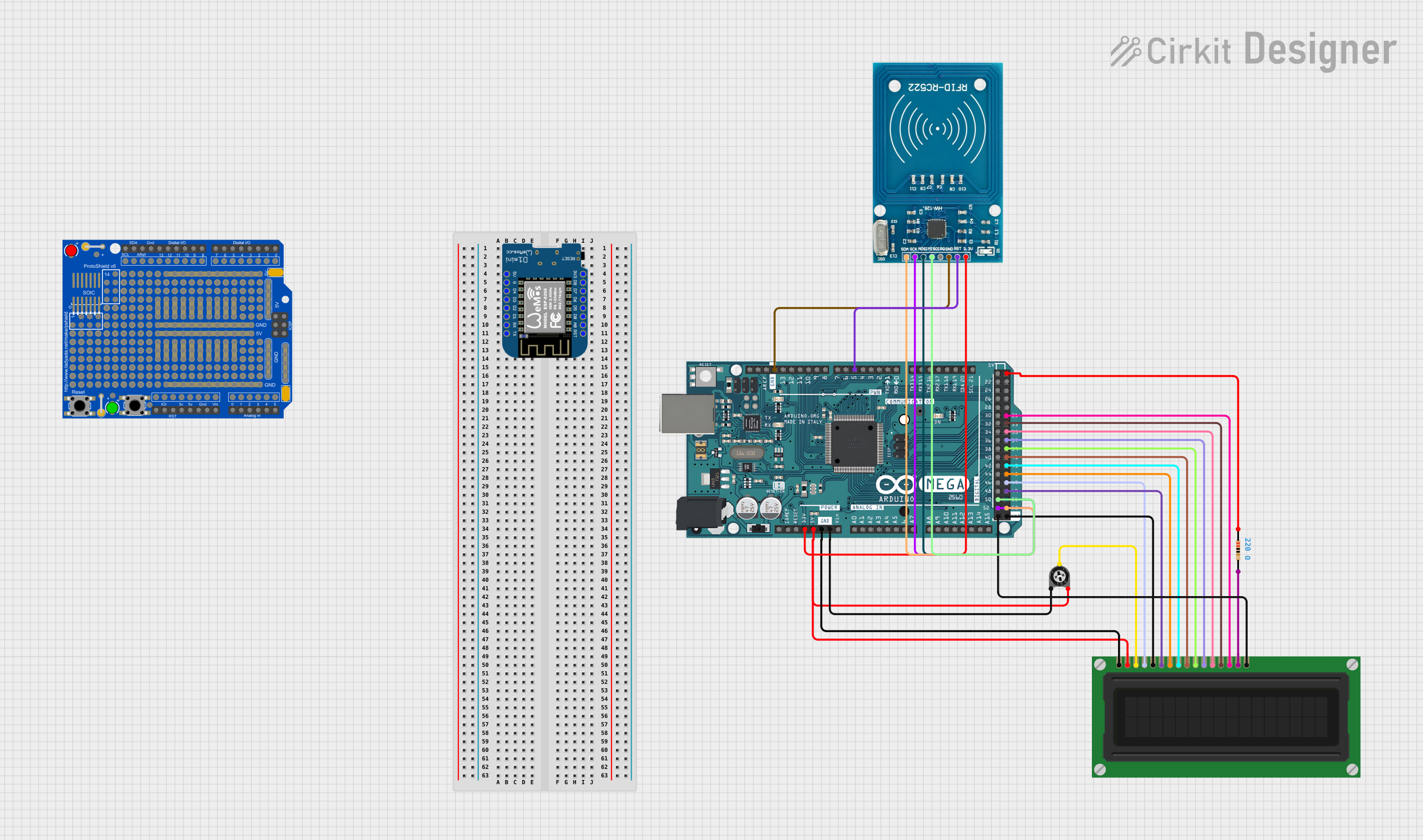
This circuit integrates various electronic components, including a microcontroller, an LCD display, a trimmer potentiometer, a resistor, an RFID module, and a prototyping shield. The primary controller of the circuit is an Arduino Mega 2560, which interfaces with an LCD display for visual output and an RFID-RC522 module for RFID communication. A trimmer potentiometer is used to adjust the contrast of the LCD, and a resistor is connected to provide backlighting for the display. The circuit is designed for modularity and expandability, as evidenced by the inclusion of the Adafruit Proto Shield R3.
Component List
Trimmer Potentiometer
- Description: A variable resistor with three terminals, used to adjust voltage levels.
- Properties: 10,000 Ohms resistance.
Resistor
- Description: A passive two-terminal electrical component that implements electrical resistance as a circuit element.
- Properties: 220 Ohms resistance.
LCD Display (16 pin)
- Description: A 16-pin liquid crystal display used for visual output.
- Properties: N/A.
Arduino Mega 2560
- Description: A microcontroller board based on the ATmega2560, with numerous digital and analog I/O pins.
- Properties: N/A.
RFID-RC522
- Description: An RFID reader/writer module.
- Properties: N/A.
Wemos D1 Mini
- Description: A mini Wi-Fi board based on ESP-8266EX.
- Properties: N/A.
Adafruit Proto Shield R3
- Description: A prototyping shield designed to facilitate the creation of custom circuits.
- Properties: N/A.
Wiring Details
Trimmer Potentiometer
- leg1: Connected to GND of Arduino Mega 2560.
- wiper: Connected to VO pin of LCD Display.
- leg2: Connected to 5V of Arduino Mega 2560.
Resistor
- pin1: Connected to 5V of Arduino Mega 2560.
- pin2: Connected to A (anode) pin of LCD Display for backlight.
LCD Display (16 pin)
- VSS: Connected to GND of Arduino Mega 2560.
- VDD: Connected to 5V of Arduino Mega 2560.
- VO: Connected to wiper of Trimmer Potentiometer.
- RS: Connected to D47 of Arduino Mega 2560.
- R_W: Connected to GND of Arduino Mega 2560.
- E: Connected to D49 of Arduino Mega 2560.
- DB0 - DB7: Connected to D45, D43, D41, D39, D37, D35, D33, and D31 of Arduino Mega 2560 respectively.
- A: Connected to pin2 of Resistor.
- K: Connected to GND of Arduino Mega 2560.
RFID-RC522
- VCC (3.3V): Connected to 3V3 of Arduino Mega 2560.
- RST: Connected to D5 PWM of Arduino Mega 2560.
- GND: Connected to GND of Arduino Mega 2560.
- SCK: Connected to D52 of Arduino Mega 2560.
- MISO: Connected to D50 of Arduino Mega 2560.
- SDA: Connected to D53 of Arduino Mega 2560.
- MOSI: Connected to D51 of Arduino Mega 2560.
Documented Code
Arduino Mega 2560 - sketch.ino
void setup() {
  // put your setup code here, to run once:

}

void loop() {
  // put your main code here, to run repeatedly:

}
Arduino Mega 2560 - documentation.txt
(No additional documentation provided)
This concludes the documentation for the given circuit. The circuit is designed for basic interfacing between the Arduino Mega 2560 and peripheral components like the LCD display and RFID-RC522 module. The code provided is a template and will need to be populated with functional code to control the LCD and communicate with the RFID module.