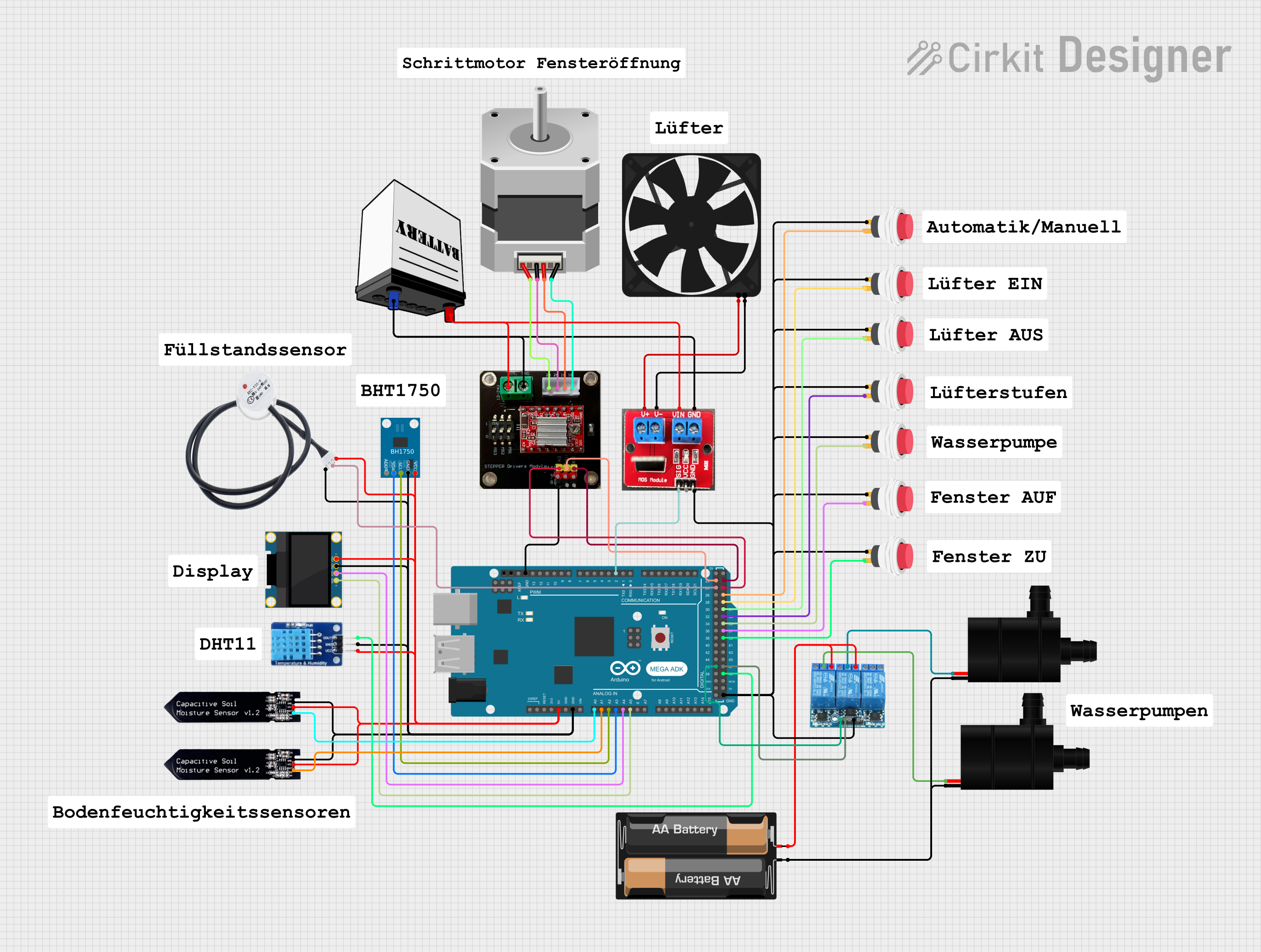
Arduino Mega ADK Automated Plant Watering and Environmental Monitoring System

Circuit Documentation
Summary
The circuit in question appears to be a complex system designed to interface with various sensors and actuators through an Arduino Mega ADK (Rev3) microcontroller. The system includes environmental sensors (BH1750 light sensor, DHT11 temperature and humidity sensor, non-contact water level sensor, and soil moisture sensors), an OLED display for user interface, a relay module to control water pumps, a MOSFET driver (IRF520) for a fan, a stepper motor with its driver (A4988), and multiple push switches for user input. The circuit is powered by a combination of a 12V battery, a 2 x AA battery mount, and the Arduino's 5V output.
Component List
Sensors
- BH1750: A digital light sensor for measuring ambient light intensity.
- DHT11: A sensor for measuring temperature and humidity.
- Non-contact water level sensor: A sensor to detect the presence of water without direct contact.
- Soil moisture sensors: Sensors to measure the moisture level in the soil.
Actuators
- Water Pumps: Devices used to move water from one place to another.
- Fan: An electric fan controlled by a MOSFET.
- Stepper Motor (Bipolar): A motor that moves in discrete steps, used for precise control of motion.
Display
- OLED 128x64 I2C Monochrome Display: A small screen for displaying data or user interface elements.
Power
- 3 Channel Relay 5V: A module with three relays to control high power devices.
- IRF520 PWM: A MOSFET driver module for controlling devices like motors and LEDs with a PWM signal.
- 2 x AA Battery Mount: A battery holder for two AA batteries.
- 12V Battery: A battery providing a 12V power source.
Control
- Arduino Mega ADK (Rev3): A microcontroller board based on the ATmega2560, with numerous digital and analog inputs/outputs.
- A4988 on Breakout Board: A stepper motor driver module.
User Input
- 2Pin Push Switches: Simple switches for user input.
Miscellaneous
- Comments: Placeholder components that may represent annotations or notes in the circuit design.
Wiring Details
BH1750 Light Sensor
- VCC: Connected to 5V power supply.
- GND: Connected to ground.
- SCL: Connected to Arduino's A2 (Analog input).
- SDA: Connected to Arduino's A3 (Analog input).
DHT11 Temperature and Humidity Sensor
- DATA: Connected to Arduino's D49 (Digital I/O).
- VCC: Connected to 5V power supply.
- GND: Connected to ground.
Non-contact Water Level Sensor
- VCC: Connected to 5V power supply.
- GND: Connected to ground.
- SIG: Connected to Arduino's D24 (Digital I/O).
Soil Moisture Sensors
- VCC: Connected to 5V power supply.
- GND: Connected to ground.
- AOUT: Connected to Arduino's A0 and A1 (Analog inputs).
OLED 128x64 I2C Monochrome Display
- VDD: Connected to 5V power supply.
- GND: Connected to ground.
- SCK: Connected to Arduino's A4 (Analog input).
- SDA: Connected to Arduino's A5 (Analog input).
3 Channel Relay 5V
- VCC: Connected to 5V power supply.
- GND: Connected to ground.
- COMMON: Connected to Water Pumps' VCC.
- NO: Connected to + of the 2 x AA Battery Mount.
- CH1, CH2, CH3: Connected to Arduino's D46, D47, and not used respectively.
Water Pumps
- VCC: Connected to Relay COMMON.
- GND: Connected to - of the 2 x AA Battery Mount.
IRF520 PWM
- V+: Connected to Fan's 5V.
- V-: Connected to Fan's GND.
- Vin: Connected to 12V Battery's VCC.
- GND: Connected to ground.
- SIG: Connected to Arduino's D2 PWM (Digital I/O).
Fan
- 5V: Connected to IRF520's V+.
- GND: Connected to IRF520's V-.
12V Battery
- VCC: Connected to IRF520's Vin and A4988's VIN (12-24V).
- GND: Connected to ground.
Stepper Motor (Bipolar)
- D, B, C, A: Connected to A4988's 1B, 1A, 2A, 2B respectively.
A4988 on Breakout Board
- VIN (12-24V): Connected to 12V Battery's VCC.
- GND: Connected to ground.
- 1A, 1B, 2A, 2B: Connected to Stepper Motor's B, D, C, A respectively.
- ENABLE: Connected to Arduino's D25 (Digital I/O).
- STEP: Connected to Arduino's D22 (Digital I/O).
- DIR: Connected to Arduino's D23 (Digital I/O).
2Pin Push Switches
- Input +: Connected to ground.
- Output +: Connected to Arduino's D37, D39, D35, D27, D29, D31, D33 (Digital I/Os).
Documented Code
No code was provided for the microcontrollers in the circuit. Therefore, this section is left blank until the relevant code is made available.