
ESP32-Based Smart Environment Monitoring System with Ethernet Connectivity
View and Edit Project In Cirkit Designer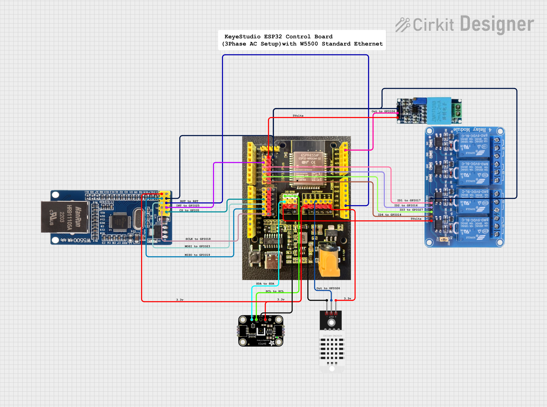
Circuit Documentation
Summary
This circuit integrates various components to perform multiple functions, including environmental sensing, Ethernet communication, and relay control. The core of the circuit is the Keyestudio Control Board for ESP32, which interfaces with an Ethernet module (W5500), a voltage sensor, a DHT22 temperature and humidity sensor, an Adafruit SHTC3 STEMMA QT sensor, and a 4-channel 5V relay module. The ESP32 board manages data acquisition from the sensors, controls the relays, and communicates over Ethernet using the W5500 module.
Component List
Keyestudio Control Board for ESP32
- Microcontroller board based on the ESP32 chip
- Features a variety of GPIO pins, power pins, and communication interfaces
Module Ethernet W5500
- Ethernet module that enables network connectivity
- Communicates with the microcontroller via SPI interface
Voltage Sensor
- Measures voltage in the circuit
- Outputs an analog voltage corresponding to the measured voltage
DHT22
- Sensor for measuring temperature and humidity
- Provides digital output
Adafruit SHTC3 STEMMA QT
- High-accuracy temperature and humidity sensor
- Uses I2C communication
Relay 4 Channel 5v
- 4-channel relay module for controlling high power devices
- Each channel can be controlled independently via GPIO pins
Comments
- Several comment components are listed, which are likely placeholders or notes within the circuit design and do not represent physical components.
Wiring Details
Keyestudio Control Board for ESP32
5Vconnected to Voltage SensorVccand Relay 4 Channel 5vVCCGNDconnected to Module Ethernet W5500GND, Voltage SensorGnd, DHT22-, Adafruit SHTC3 STEMMA QTGND, and Relay 4 Channel 5vGNDGPIO25connected to Module Ethernet W5500INTGPIO17connected to Relay 4 Channel 5vIN1GPIO16connected to Relay 4 Channel 5vIN2GPIO27connected to Relay 4 Channel 5vIN3GPIO14connected to Relay 4 Channel 5vIN4GPIO5connected to Module Ethernet W5500NCGPIO23connected to Module Ethernet W5500MOSIGPIO19connected to Module Ethernet W5500MISOGPIO18connected to Module Ethernet W5500SCKRSTconnected to Module Ethernet W5500RSTGPIO36 (VP)connected to Voltage SensorOutGPIO33connected to DHT22OutSCLconnected to Adafruit SHTC3 STEMMA QTSCLSDAconnected to Adafruit SHTC3 STEMMA QTSDA3V3connected to Module Ethernet W55003.3V, Adafruit SHTC3 STEMMA QT3.3V, and DHT22+
Module Ethernet W5500
INTconnected to ESP32GPIO25RSTconnected to ESP32RSTGNDconnected to ESP32GND5Vnot connectedSCKconnected to ESP32GPIO18SSnot connectedMOSIconnected to ESP32GPIO23MISOconnected to ESP32GPIO193.3Vconnected to ESP323V3
Voltage Sensor
Vccconnected to ESP325VOutconnected to ESP32GPIO36 (VP)Gndconnected to ESP32GND
DHT22
+connected to ESP323V3Outconnected to ESP32GPIO33-connected to ESP32GND
Adafruit SHTC3 STEMMA QT
VCCnot connected3.3Vconnected to ESP323V3GNDconnected to ESP32GNDSCLconnected to ESP32SCLSDAconnected to ESP32SDA
Relay 4 Channel 5v
GNDconnected to ESP32GNDIN1connected to ESP32GPIO17IN2connected to ESP32GPIO16IN3connected to ESP32GPIO27IN4connected to ESP32GPIO14VCCconnected to ESP325VCOM1,COM2,COM3,COM4,NO1,NO2,NO3,NO4,NC1,NC2,NC3,NC4not connected
Documented Code
No code has been provided for the microcontrollers in the circuit. The documentation of the code would typically include descriptions of the functions, initialization procedures, main loop, and any interrupt service routines. It would also detail how the code interacts with the hardware components listed above, such as reading sensor data, controlling the relay states, and managing Ethernet communication.