
Circuit Documentation
Summary
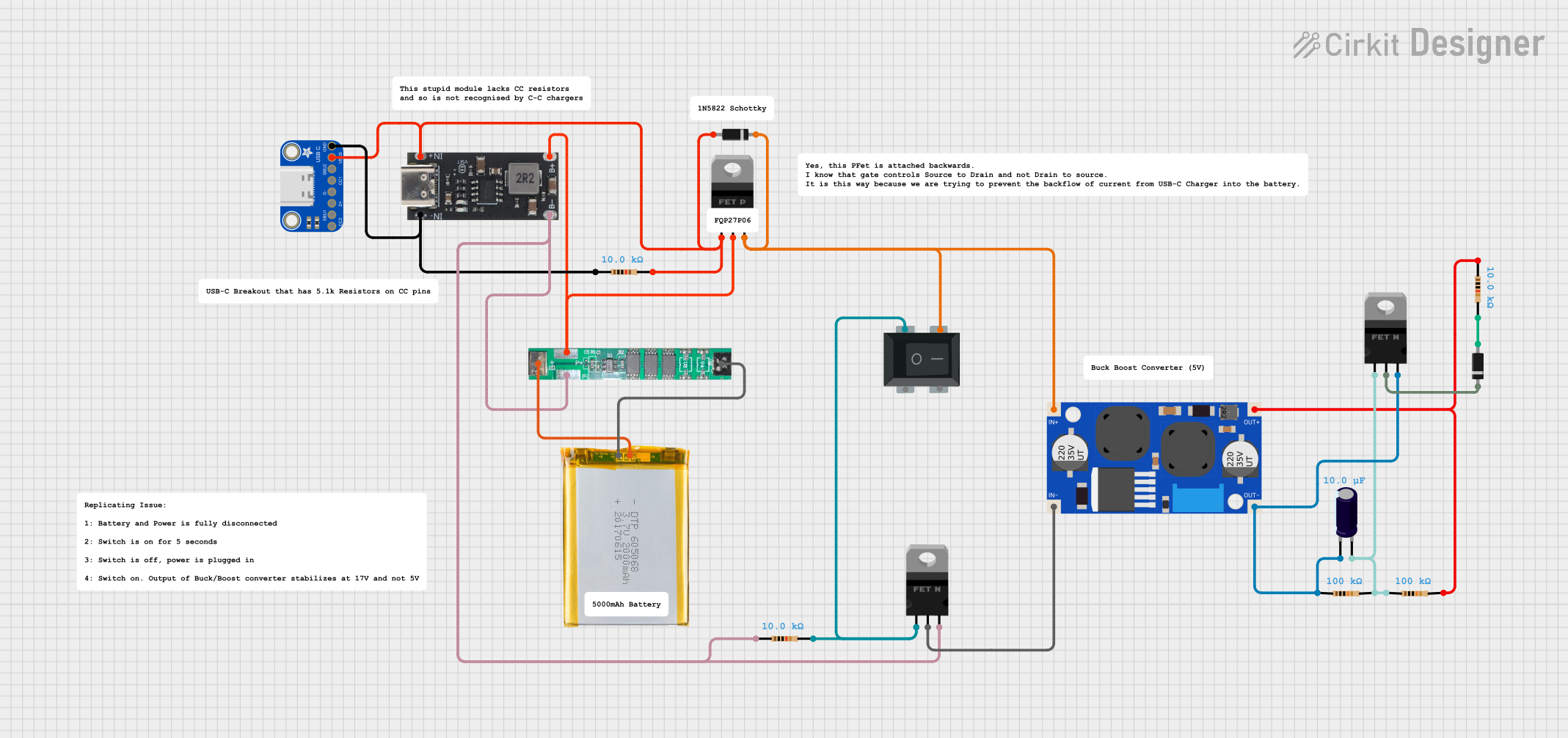
This document provides a detailed overview of a circuit design that includes various components such as a boost converter, MOSFETs, capacitors, resistors, diodes, a battery management system (BMS), a USB Type C breakout, and a battery. The circuit is designed to manage power distribution and conversion, likely for a portable electronic device. The document includes a component list, wiring details, and code documentation.
Component List
XL6009E1 Boost Converter
- Description: Boost converter used to step up voltage.
- Pins: IN+, IN-, OUT-, OUT+
nMOS Transistor (MOSFET)
- Description: n-channel MOSFET used for switching.
- Pins: gate, drain, source
Electrolytic Capacitor
- Description: Capacitor used for filtering.
- Pins: -, +
- Properties:
- Capacitance: 0.00001 Farads
Resistor (100k Ohms)
- Description: Resistor used for current limiting or voltage division.
- Pins: pin1, pin2
- Properties:
- Resistance: 100000 Ohms
Resistor (10k Ohms)
- Description: Resistor used for current limiting or voltage division.
- Pins: pin1, pin2
- Properties:
- Resistance: 10000 Ohms
Diode
- Description: Diode used for current direction control.
- Pins: cathode, anode
RockerSwitch4Pin
- Description: 4-pin rocker switch used for user input.
- Pins: 1, 3, 2, 4
BMS 1S1P 3.7V 3A (for 18650)
- Description: Battery management system for a single-cell 18650 battery.
- Pins: B+, P+, P-, B-
pMOS Transistor (MOSFET)
- Description: p-channel MOSFET used for switching.
- Pins: gate, drain, source
Adafruit USB Type C Breakout
- Description: USB Type C breakout board for power and data connections.
- Pins: GND, VBUS, SBU2, CC1, D-, D+, SBU1, CC2
2000mAh Battery
- Description: 2000mAh battery for power supply.
- Pins: VCC, GND
IP2312
- Description: Power management IC.
- Pins: B-, B+, IN-, IN+
Wiring Details
XL6009E1 Boost Converter
IN+ is connected to:
- RockerSwitch4Pin pin 3
- Diode cathode
- pMOS Transistor (MOSFET) source
IN- is connected to:
- nMOS Transistor (MOSFET) drain
OUT- is connected to:
- nMOS Transistor (MOSFET) source
- Electrolytic Capacitor -
- Resistor (100k Ohms) pin1
OUT+ is connected to:
- Resistor (10k Ohms) pin1
- Resistor (100k Ohms) pin2
nMOS Transistor (MOSFET)
gate is connected to:
- Resistor (10k Ohms) pin2
- RockerSwitch4Pin pin 1
drain is connected to:
- XL6009E1 Boost Converter IN-
source is connected to:
- Electrolytic Capacitor -
- Resistor (100k Ohms) pin1
- XL6009E1 Boost Converter OUT-
Electrolytic Capacitor
- is connected to:
- nMOS Transistor (MOSFET) source
- Resistor (100k Ohms) pin1
- XL6009E1 Boost Converter OUT-
+ is connected to:
- nMOS Transistor (MOSFET) gate
- Resistor (100k Ohms) pin2
Resistor (100k Ohms)
pin1 is connected to:
- nMOS Transistor (MOSFET) source
- Electrolytic Capacitor -
- XL6009E1 Boost Converter OUT-
pin2 is connected to:
- XL6009E1 Boost Converter OUT+
- Resistor (10k Ohms) pin1
Resistor (10k Ohms)
pin1 is connected to:
- XL6009E1 Boost Converter OUT+
- Resistor (100k Ohms) pin2
pin2 is connected to:
- nMOS Transistor (MOSFET) gate
- RockerSwitch4Pin pin 1
Diode
cathode is connected to:
- XL6009E1 Boost Converter IN+
- RockerSwitch4Pin pin 3
- pMOS Transistor (MOSFET) source
anode is connected to:
- Adafruit USB Type C Breakout VBUS
- Resistor (10k Ohms) pin2
- IP2312 IN+
RockerSwitch4Pin
pin 1 is connected to:
- Resistor (10k Ohms) pin2
- nMOS Transistor (MOSFET) gate
pin 3 is connected to:
- XL6009E1 Boost Converter IN+
- Diode cathode
- pMOS Transistor (MOSFET) source
BMS 1S1P 3.7V 3A (for 18650)
B+ is connected to:
- IP2312 B+
- pMOS Transistor (MOSFET) drain
P+ is connected to:
- IP2312 B+
- pMOS Transistor (MOSFET) drain
P- is connected to:
- IP2312 B-
- nMOS Transistor (MOSFET) source
B- is connected to:
- IP2312 B-
- nMOS Transistor (MOSFET) source
pMOS Transistor (MOSFET)
gate is connected to:
- Adafruit USB Type C Breakout VBUS
- Diode anode
- Resistor (10k Ohms) pin2
- IP2312 IN+
drain is connected to:
- IP2312 B+
- BMS 1S1P 3.7V 3A (for 18650) P+
source is connected to:
- XL6009E1 Boost Converter IN+
- RockerSwitch4Pin pin 3
- Diode cathode
Adafruit USB Type C Breakout
GND is connected to:
- Resistor (10k Ohms) pin1
- IP2312 IN-
VBUS is connected to:
- Diode anode
- Resistor (10k Ohms) pin2
- IP2312 IN+
- pMOS Transistor (MOSFET) gate
2000mAh Battery
VCC is connected to:
- BMS 1S1P 3.7V 3A (for 18650) B+
GND is connected to:
- BMS 1S1P 3.7V 3A (for 18650) B-
IP2312
B- is connected to:
- BMS 1S1P 3.7V 3A (for 18650) P-
- nMOS Transistor (MOSFET) source
B+ is connected to:
- BMS 1S1P 3.7V 3A (for 18650) P+
- pMOS Transistor (MOSFET) drain
IN- is connected to:
- Adafruit USB Type C Breakout GND
- Resistor (10k Ohms) pin1
IN+ is connected to:
- Adafruit USB Type C Breakout VBUS
- Diode anode
- Resistor (10k Ohms) pin2
- pMOS Transistor (MOSFET) gate
Code Documentation
There is no code provided for this circuit.
This document provides a comprehensive overview of the circuit, including a detailed component list and wiring details. This should help in understanding the circuit's design and functionality.