
Raspberry Pi 4B-Based Flame Detection and Motor Control System
View and Edit Project In Cirkit Designer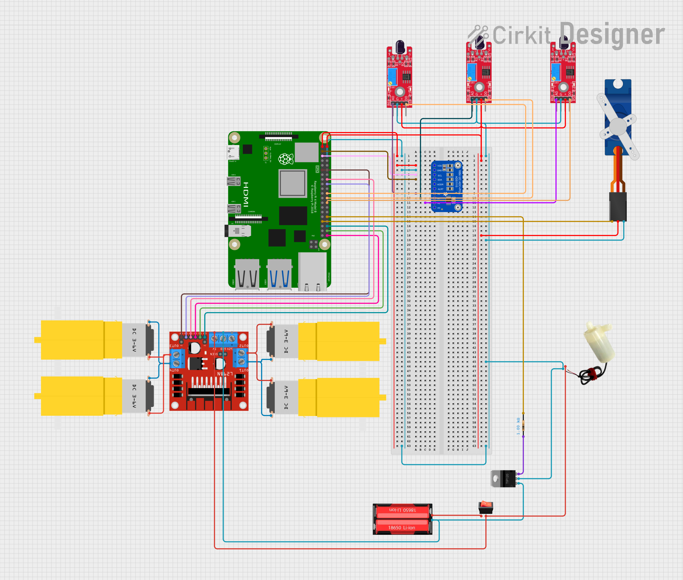
Circuit Documentation
Summary
This circuit is designed to interface a Raspberry Pi 4B with various sensors, actuators, and a motor driver. It includes flame sensors for detecting fire or flames, a motor driver to control hobby motors, a servo motor for precision control, a Darlington transistor for high-current applications, and an ADC for analog signal processing. The circuit is powered by a 18650 Li-Ion battery, and a rocker switch is used to control the power supply. The Raspberry Pi 4B serves as the central processing unit, interfacing with the I2C ADC and controlling the GPIOs for various functions.
Component List
Raspberry Pi 4B
- Microcontroller and central processing unit of the circuit.
- Provides GPIO pins for interfacing with sensors and actuators.
- Supplies power to certain components via its 3.3V and 5V pins.
KY-026 Flame Sensor
- Detects flames or fire.
- Outputs an analog signal (AO) and a digital output (DO).
Motor Amarillo Motorreductor Hobby
- A hobby motor used for driving mechanical loads.
L298N DC Motor Driver
- Controls the direction and speed of motors.
- Interfaces with the Raspberry Pi via GPIO pins.
18650 Li-Ion Battery
- Provides power to the circuit.
Rocker Switch
- Controls the power supply from the battery to the circuit.
5V Mini Water Pump
- An actuator that pumps water when powered.
Tower Pro SG90 Servo
- A servo motor for precise angular control.
TIP120 Hi-Current Darlington Transistor
- Used for controlling high-current loads.
Resistor
- A 1000 Ohm resistor used for current limiting or voltage division.
Adafruit ADS1115 16Bit I2C ADC
- An analog-to-digital converter that interfaces with the Raspberry Pi via I2C.
Wiring Details
Raspberry Pi 4B
3V3connected to Adafruit ADS1115 VDD.5Vconnected to KY-026 Flame Sensors VCC, Tower Pro SG90 servo +5V.GNDconnected to common ground net.GPIO2(SDA) connected to Adafruit ADS1115 SDA.GPIO3(SCL) connected to Adafruit ADS1115 SCL.GPIO7,GPIO8,GPIO25connected to KY-026 Flame Sensors DO.GPIO12connected to Resistor pin2.GPIO13connected to Tower Pro SG90 servo Signal.GPIO16,GPIO17,GPIO20,GPIO21,GPIO23,GPIO24connected to L298N DC motor driver control pins.
KY-026 Flame Sensors
AOconnected to Adafruit ADS1115 AIN0, AIN1, AIN2.GNDconnected to common ground net.VCCconnected to Raspberry Pi 4B 5V.DOconnected to Raspberry Pi 4B GPIO7, GPIO8, GPIO25.
Motor Amarillo Motorreductor Hobby
vccconnected to L298N DC motor driver OUT1, OUT2, OUT3, OUT4.GNDconnected to L298N DC motor driver OUT1, OUT2, OUT3, OUT4.
L298N DC Motor Driver
ENB,ENAconnected to Raspberry Pi 4B GPIO17, GPIO16.IN1,IN2,IN3,IN4connected to Raspberry Pi 4B GPIO20, GPIO21, GPIO23, GPIO24.OUT1,OUT2,OUT3,OUT4connected to Motor Amarillo motorreductor hobby vcc, GND.GNDconnected to TIP120 Hi-Current Darlington Transistor BASE.5Vconnected to 5v mini water pump positive pin.
18650 Li-Ion Battery
Positiveconnected to rocker switch input.Negativeconnected to common ground net.
Rocker Switch
outputconnected to L298N DC motor driver 5V.inputconnected to 18650 Li-Ion battery Positive.
5V Mini Water Pump
positive pinconnected to L298N DC motor driver 5V.negative pinconnected to common ground net.
Tower Pro SG90 Servo
Signalconnected to Raspberry Pi 4B GPIO13.+5Vconnected to Raspberry Pi 4B 5V.GNDconnected to common ground net.
TIP120 Hi-Current Darlington Transistor
BASEconnected to L298N DC motor driver GND.COLLECTORconnected to common ground net.EMITTERconnected to Resistor pin1.
Resistor
pin1connected to TIP120 Hi-Current Darlington Transistor EMITTER.pin2connected to Raspberry Pi 4B GPIO12.
Adafruit ADS1115 16Bit I2C ADC
VDDconnected to Raspberry Pi 4B 3V3.GNDconnected to common ground net.SCLconnected to Raspberry Pi 4B GPIO3.SDAconnected to Raspberry Pi 4B GPIO2.AIN0,AIN1,AIN2connected to KY-026 Flame Sensors AO.
Documented Code
No code has been provided for the microcontrollers in the circuit. The Raspberry Pi 4B would typically be programmed in Python or another suitable language to interact with the I2C ADC, read the digital outputs from the flame sensors, control the servo motor via PWM, and manage the motor driver. The code would include initializing the GPIO pins, setting up the I2C communication, reading sensor data, and controlling the actuators based on the sensor inputs or other logic.