
ESP32-Based Health Monitoring System with MAX30102 and Temperature Sensors
View and Edit Project In Cirkit Designer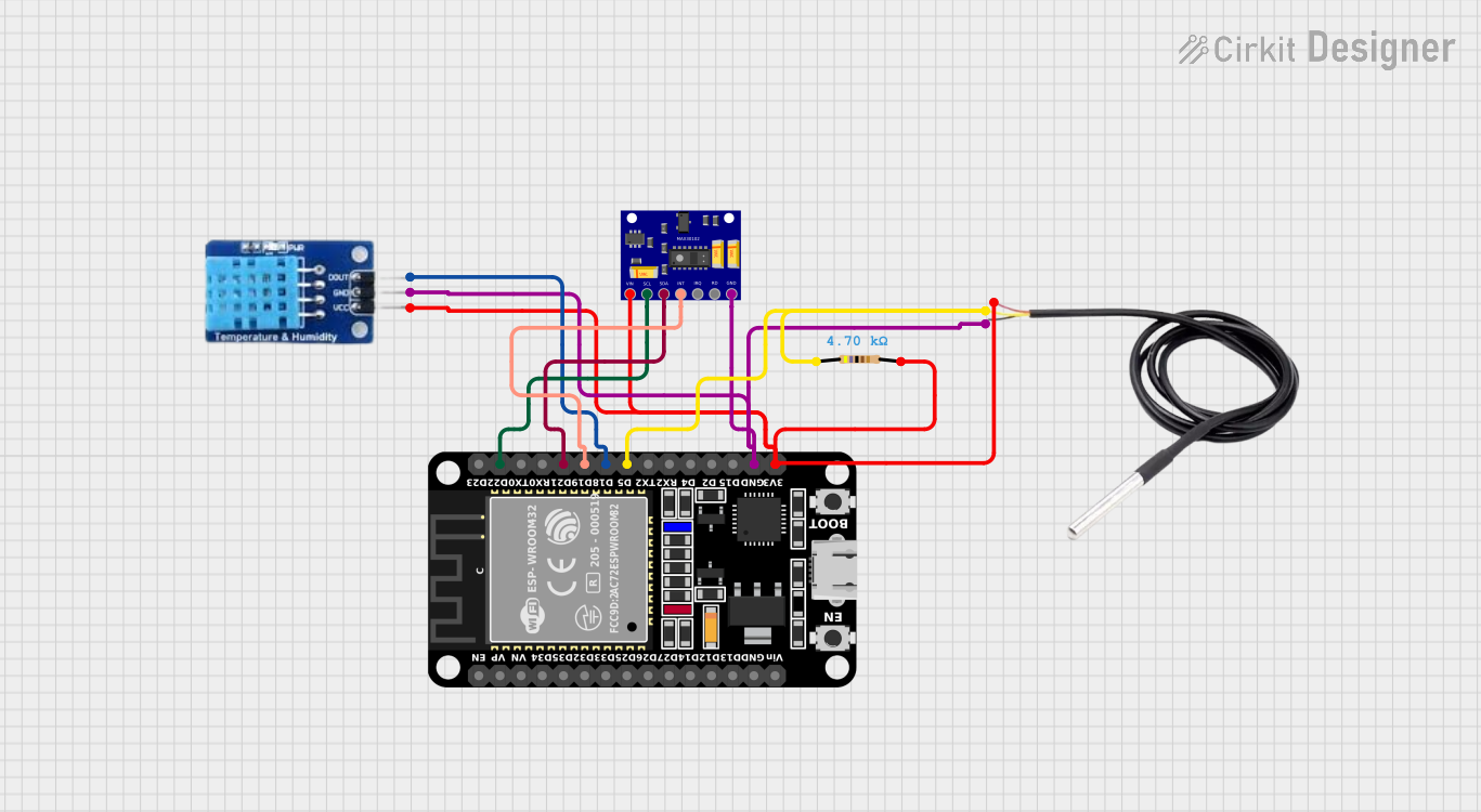
Circuit Documentation
Summary
The circuit in question is designed to monitor vital signs using a MAX30102 heart rate and oxygen sensor, along with temperature and humidity readings from a DS18B20 temperature sensor and a DHT11 humidity and temperature sensor. The ESP32 microcontroller serves as the central processing unit, interfacing with the sensors and managing data communication. A resistor is included in the circuit for the proper operation of the DS18B20 sensor. The circuit is powered by a 3.3V supply from the ESP32, and the ground connections are shared among all components.
Component List
ESP32 (30 pin)
- Description: A microcontroller with Wi-Fi and Bluetooth capabilities, featuring a wide range of GPIO pins.
- Purpose: Acts as the central processing unit for the circuit, interfacing with sensors and managing data communication.
MAX30102 Heart Rate and Oxygen Sensor
- Description: An integrated pulse oximetry and heart-rate monitor sensor module.
- Purpose: Measures heart rate and blood oxygen levels.
DS18B20
- Description: A digital thermometer providing 9-bit to 12-bit Celsius temperature measurements.
- Purpose: Measures temperature with high accuracy.
DHT11
- Description: A basic, ultra-low-cost digital temperature and humidity sensor.
- Purpose: Provides ambient temperature and humidity readings.
Resistor (4.7k Ohms)
- Description: A passive two-terminal electrical component that implements electrical resistance as a circuit element.
- Purpose: Used as a pull-up resistor for the DS18B20 sensor signal line.
Wiring Details
ESP32 (30 pin)
- D22: Connected to SCL pin of MAX30102 sensor for I2C communication.
- D21: Connected to SDA pin of MAX30102 sensor for I2C communication.
- D19: Connected to INT pin of MAX30102 sensor for interrupt signaling.
- D18: Connected to DATA pin of DHT11 sensor for data communication.
- D5: Connected to signal pin of DS18B20 sensor through a 4.7k Ohm resistor.
- GND: Common ground shared with all components.
- 3V3: Provides power to MAX30102, DS18B20, and DHT11 sensors, and the 4.7k Ohm resistor.
MAX30102 Heart Rate and Oxygen Sensor
- SCL: Connected to D22 pin of ESP32 for I2C communication.
- SDA: Connected to D21 pin of ESP32 for I2C communication.
- INT: Connected to D19 pin of ESP32 for interrupt signaling.
- GND: Shared ground connection.
- VIN: Powered by the 3.3V output from ESP32.
DS18B20
- Signal: Connected to D5 pin of ESP32 through a 4.7k Ohm resistor.
- GND: Shared ground connection.
- VCC: Powered by the 3.3V output from ESP32.
DHT11
- DATA: Connected to D18 pin of ESP32 for data communication.
- GND: Shared ground connection.
- VCC: Powered by the 3.3V output from ESP32.
Resistor (4.7k Ohms)
- Pin1: Connected to signal pin of DS18B20 sensor.
- Pin2: Connected to the 3.3V power supply from ESP32.
Documented Code
There is no code provided for the microcontroller at this time. When code is available, it should be documented here with explanations for each function and routine, including setup and loop functions, sensor reading and processing, and any communication protocols used (e.g., I2C, serial communication).
This documentation provides an overview of the circuit's components, their purposes, and the wiring connections between them. Further details, such as schematic diagrams, PCB layouts, and code implementation, would be necessary for a complete understanding and replication of the circuit.