Cirkit Designer
Your all-in-one circuit design IDE
Home /
Project Documentation
IR Obstacle Detection System with Relay-Controlled Gearmotors and Boost Converters
Circuit Documentation
Summary of the Circuit
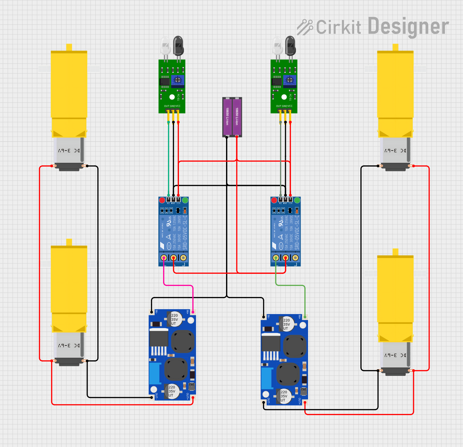
This circuit appears to be designed for controlling gearmotors based on the input from IR obstacle sensors. It includes two FC-51 IR Obstacle Sensors that likely serve as the input devices to detect obstacles. The circuit also contains two KF-301 Relays which are probably used to switch the gearmotors on and off. The power for the circuit is provided by a pair of 18650 Li-ion batteries, and the voltage is regulated and boosted by two XL6009E1 Boost Converters. There are also four Gearmotor DC / Motorreductor components that are the actuators of the circuit.
Component List
FC-51 IR Obstacle Sensor
- Pins: Out, GND, VCC
- Description: An infrared sensor capable of detecting obstacles and changes in surface reflectivity.
XL6009E1 Boost Converter
- Pins: IN+, IN-, OUT-, OUT+
- Description: A DC-DC boost converter module that steps up voltage from its input to its output.
KF-301 Relay
- Pins: signal, power, ground, NC, C, NO
- Description: An electromechanical switch used to control a high power circuit with a low power signal.
Gearmotor DC / Motorreductor
- Pins: Pin1, Pin2
- Description: A DC gearmotor that converts electrical power into mechanical motion.
18650 Li-ion Battery x 2
- Pins: +, -
- Description: A rechargeable battery providing the power source for the circuit.
Wiring Details
FC-51 IR Obstacle Sensor
- Out: Connected to the signal pin of a KF-301 Relay.
- GND: Connected to the negative terminal of the 18650 Li-ion Battery and ground pins of KF-301 Relay and XL6009E1 Boost Converter.
- VCC: Connected to the positive terminal of the 18650 Li-ion Battery and power pins of KF-301 Relay.
XL6009E1 Boost Converter
- IN+: Connected to the NO pin of a KF-301 Relay.
- IN-: Connected to the negative terminal of the 18650 Li-ion Battery.
- OUT-: Connected to Pin2 of two Gearmotor DC / Motorreductor components.
- OUT+: Connected to Pin1 of two Gearmotor DC / Motorreductor components.
KF-301 Relay
- signal: Connected to the Out pin of an FC-51 IR Obstacle Sensor.
- power: Connected to the positive terminal of the 18650 Li-ion Battery.
- ground: Connected to the negative terminal of the 18650 Li-ion Battery.
- NC: Not connected in this circuit.
- C: Connected to the positive terminal of the 18650 Li-ion Battery.
- NO: Connected to the IN+ pin of an XL6009E1 Boost Converter.
Gearmotor DC / Motorreductor
- Pin1: Connected to the OUT+ pin of an XL6009E1 Boost Converter.
- Pin2: Connected to the OUT- pin of an XL6009E1 Boost Converter.
18650 Li-ion Battery x 2
- +: Connected to the VCC pins of FC-51 IR Obstacle Sensors and power pins of KF-301 Relays.
- -: Connected to the GND pins of FC-51 IR Obstacle Sensors, ground pins of KF-301 Relays, and IN- pins of XL6009E1 Boost Converters.
Documented Code
There is no code provided for any microcontrollers in this circuit. If there were microcontrollers involved, their code would be documented in this section.