ESP32-Based Environmental Monitoring System with Ultrasonic, Gas, and IR Sensors

Circuit Documentation
Summary of the Circuit
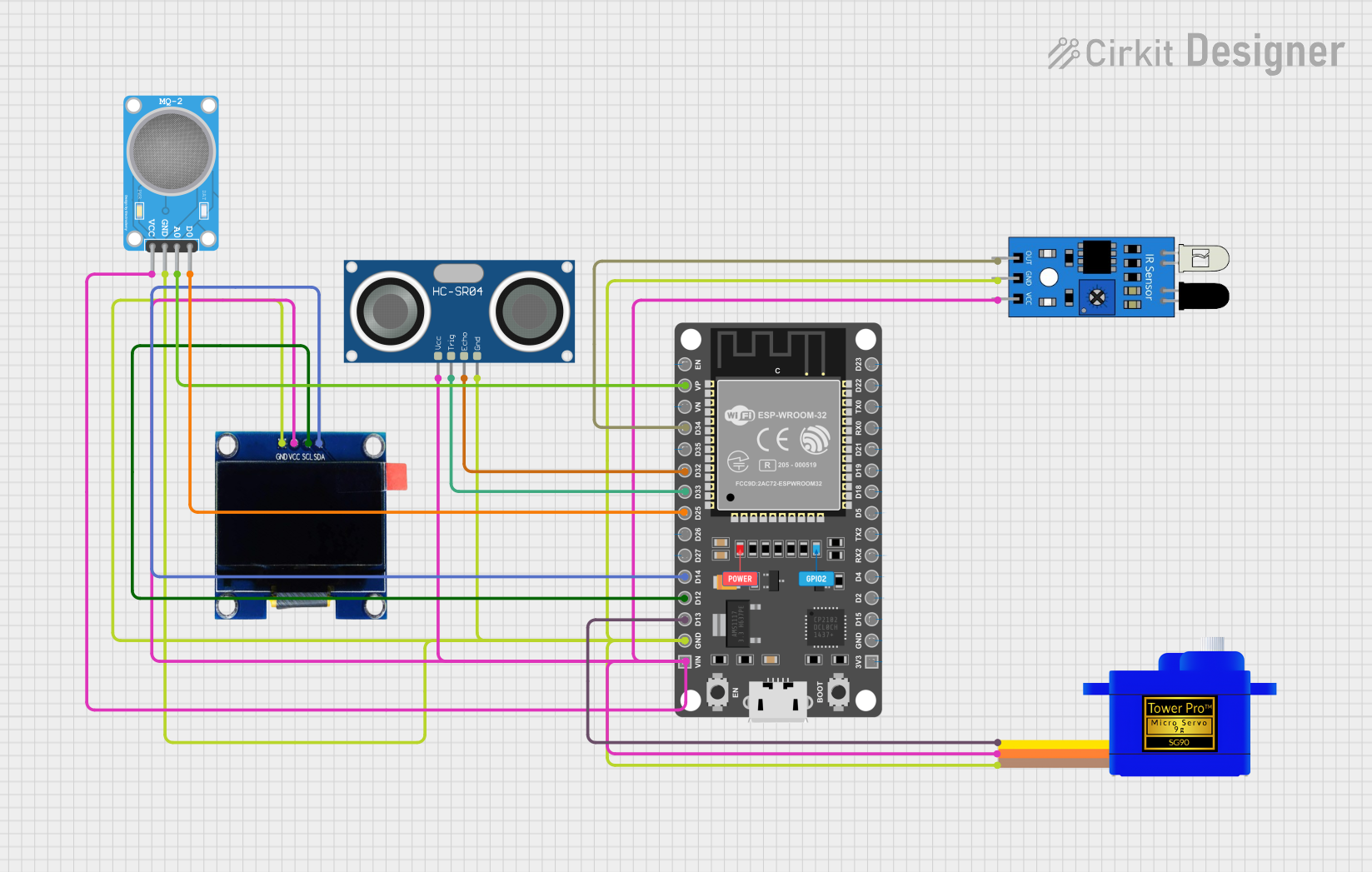
This circuit integrates various sensors and output devices with an ESP32 microcontroller to form a multifunctional system. The ESP32 serves as the central processing unit, interfacing with an ultrasonic sensor (HC-SR04), an infrared sensor, a servomotor (SG90), an OLED display, and an MQ-2 gas sensor. The circuit is designed to monitor and respond to environmental inputs, display information, and actuate a mechanical response via the servomotor.
Component List
ESP 32 DEVKIT V1 (30 pins)
- Description: A microcontroller board based on the ESP32 chip, featuring Wi-Fi and Bluetooth connectivity, with a wide range of GPIO pins for interfacing with various sensors and actuators.
- Purpose: Acts as the central processing unit for the circuit, reading sensor data, controlling the OLED display, and driving the servomotor.
HC-SR04 Ultrasonic Sensor
- Description: An ultrasonic ranging module that uses sonar to determine the distance to an object.
- Purpose: Provides distance measurements to the ESP32 for processing and decision-making.
IR Sensor
- Description: An infrared sensor capable of detecting obstacles and changes in surface reflectivity.
- Purpose: Serves as an input device to detect nearby objects or movements.
Servomotor SG90
- Description: A small and lightweight servo motor capable of precise angular positioning.
- Purpose: Acts as an output device to perform mechanical movements based on commands from the ESP32.
OLED 1.3"
- Description: A small OLED display module for showing text and graphics.
- Purpose: Displays information such as sensor readings or system status.
MQ-2 Sensor
- Description: A gas sensor module used for detecting a variety of gases including LPG, smoke, and alcohol vapor.
- Purpose: Monitors air quality and provides gas concentration data to the ESP32.
Wiring Details
ESP 32 DEVKIT V1 (30 pins)
- VP connected to MQ-2 SENSOR A0
- D34 connected to IR Sensor Out
- D32 connected to HC-SR04 Ultrasonic Sensor ECHO
- D33 connected to HC-SR04 Ultrasonic Sensor TRIG
- D25 connected to MQ-2 SENSOR D0
- D14 connected to OLED 1.3" SDA
- D12 connected to OLED 1.3" SCL
- D13 connected to Servomotor SG90 SIG
- GND connected to all components' GND pins
- VIN connected to all components' VCC pins
HC-SR04 Ultrasonic Sensor
- VCC connected to ESP 32 DEVKIT V1 VIN
- TRIG connected to ESP 32 DEVKIT V1 D33
- ECHO connected to ESP 32 DEVKIT V1 D32
- GND connected to ESP 32 DEVKIT V1 GND
IR Sensor
- Out connected to ESP 32 DEVKIT V1 D34
- GND connected to ESP 32 DEVKIT V1 GND
- VCC connected to ESP 32 DEVKIT V1 VIN
Servomotor SG90
- SIG connected to ESP 32 DEVKIT V1 D13
- VCC connected to ESP 32 DEVKIT V1 VIN
- GND connected to ESP 32 DEVKIT V1 GND
OLED 1.3"
- SDA connected to ESP 32 DEVKIT V1 D14
- SCL connected to ESP 32 DEVKIT V1 D12
- VCC connected to ESP 32 DEVKIT V1 VIN
- GND connected to ESP 32 DEVKIT V1 GND
MQ-2 SENSOR
- A0 connected to ESP 32 DEVKIT V1 VP
- D0 connected to ESP 32 DEVKIT V1 D25
- VCC connected to ESP 32 DEVKIT V1 VIN
- GND connected to ESP 32 DEVKIT V1 GND
Documented Code
No code was provided for the microcontrollers in the circuit. To fully utilize the hardware, embedded code should be written and uploaded to the ESP32 microcontroller. The code should initialize and read from the sensors, control the servomotor, and manage the display on the OLED screen based on the sensor inputs and desired application logic.