Cirkit Designer
Your all-in-one circuit design IDE
Home /
Project Documentation
Arduino UNO Powered Push Switch Control Circuit
Circuit Documentation
Summary
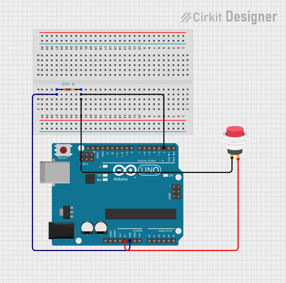
This document provides a detailed overview of a simple circuit that utilizes an Arduino UNO, a resistor, and a 2-pin push switch. The circuit is designed to interface the push switch with the Arduino, allowing for input detection. The resistor is used to pull the input pin to ground when the switch is not pressed, ensuring a stable low state.
Component List
Arduino UNO
- Description: A microcontroller board based on the ATmega328P. It is used for programming and controlling the circuit.
- Purpose: Acts as the main control unit for the circuit, processing inputs from the push switch.
Resistor
- Description: A passive electrical component that limits the flow of current in a circuit.
- Purpose: Used to pull the input pin of the push switch to ground when the switch is not pressed, preventing floating states.
2Pin Push Switch
- Description: A simple switch that can connect or disconnect two points in a circuit.
- Purpose: Provides a manual input to the Arduino, allowing the user to trigger actions in the code.
Wiring Details
Arduino UNO
- 5V Pin: Connected to the Output + pin of the 2Pin Push Switch.
Resistor
- pin1: Connected to the GND pin of the Arduino UNO.
Resistor
- pin2: Connected to the D2 pin of the Arduino UNO.
2Pin Push Switch
- Input +: Connected to pin2 of the resistor.
2Pin Push Switch
- Output +: Connected to the 5V pin of the Arduino UNO.
Documented Code
Arduino Code
void setup() {
  // put your setup code here, to run once:

}

void loop() {
  // put your main code here, to run repeatedly:

}
Documentation
This section is reserved for additional documentation or notes related to the code. Currently, there are no specific notes provided.
This concludes the documentation for the circuit. Please refer to the wiring details and component descriptions for further understanding of the circuit's functionality.