
Arduino UNO Controlled Water Level Indicator with Multicolor LED Feedback
View and Edit Project In Cirkit Designer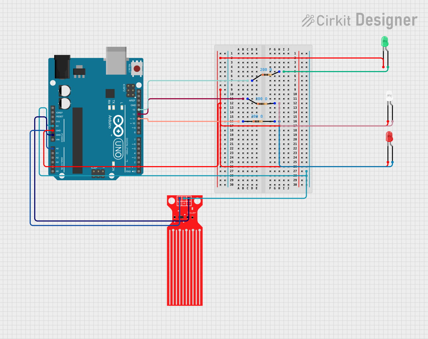
Circuit Documentation
Summary
The circuit in question is designed to monitor water levels using a sensor and indicate the level through a series of LEDs. An Arduino UNO microcontroller serves as the central processing unit, reading the sensor data and controlling the LEDs. The circuit includes three LEDs (red, green, and white), each with a corresponding resistor to limit current. The water level sensor provides an analog signal to the Arduino, which then lights up the appropriate LED based on the water level.
Component List
LEDs
- LED (Red): A two-pin red LED that lights up when activated.
- LED (Green): A two-pin green LED that lights up when activated.
- LED (White): A two-pin white LED that lights up when activated.
Resistors
- Resistor: Three resistors with a resistance of 200 Ohms each, used to limit the current through the LEDs.
Microcontroller
- Arduino UNO: A microcontroller board based on the ATmega328P, with various digital and analog I/O pins.
Sensor
- Water Level Sensor: A sensor that detects the water level and outputs an analog signal.
Wiring Details
LED (Red)
- Anode connected to a 200 Ohm resistor.
- Cathode connected to the common ground.
LED (Green)
- Anode connected to a 200 Ohm resistor.
- Cathode connected to the common ground.
LED (White)
- Anode connected to a 200 Ohm resistor.
- Cathode connected to the common ground.
Resistor (200 Ohms)
- One end connected to an LED anode.
- The other end connected to a digital pin on the Arduino UNO (D13, D12, or D11 for red, green, and white LEDs, respectively).
Arduino UNO
- Digital pins D13, D12, and D11 connected to resistors.
- Analog pin A0 connected to the signal pin of the Water Level Sensor.
- 5V and GND pins providing power to the Water Level Sensor.
- GND pin connected to the cathodes of all LEDs.
Water Level Sensor
- SIG pin connected to analog pin A0 on the Arduino UNO.
- VCC pin connected to the 5V pin on the Arduino UNO.
- GND pin connected to the GND pin on the Arduino UNO.
Documented Code
// Code for Arduino UNO to monitor water level and control LEDs
int level;
const int analog_0 = 0;
int l1 = 13; // Red LED
int l2 = 12; // Green LED
int l3 = 11; // White LED
int l4 = 10; // Unused LED

void setup() {
  Serial.begin(9600);
  pinMode(l1, OUTPUT);
  pinMode(l2, OUTPUT);
  pinMode(l3, OUTPUT);
  pinMode(l4, OUTPUT);
  pinMode(8, OUTPUT); // Unused pin
}

void loop() {
  level = analogRead(analog_0); // Read the water level
  Serial.println(level); // Print the level to the serial monitor

  // Control LEDs based on water level
  if (level > 500 && level < 550) {
    digitalWrite(l1, HIGH); // Red LED on
    digitalWrite(l2, LOW);  // Green LED off
    digitalWrite(l3, LOW);  // White LED off
    digitalWrite(l4, LOW);  // Unused LED off
  } else if (level > 600 && level < 620) {
    digitalWrite(l1, LOW);  // Red LED off
    digitalWrite(l2, HIGH); // Green LED on
    digitalWrite(l3, LOW);  // White LED off
    digitalWrite(l4, LOW);  // Unused LED off
  } else if (level > 620 && level < 630) {
    digitalWrite(l1, LOW);  // Red LED off
    digitalWrite(l2, LOW);  // Green LED off
    digitalWrite(l3, HIGH); // White LED on
    digitalWrite(l4, LOW);  // Unused LED off
  } else if (level > 630 && level < 650) {
    digitalWrite(l1, LOW);  // Red LED off
    digitalWrite(l2, LOW);  // Green LED off
    digitalWrite(l3, LOW);  // White LED off
    digitalWrite(l4, HIGH); // Unused LED on
    digitalWrite(8, HIGH);  // Unused pin on
  }
}
This code is designed to read the water level from the sensor and light up the corresponding LED based on predefined level thresholds. The serial communication is initiated for debugging purposes, and the digital pins are configured as outputs to control the LEDs. The loop function continuously reads the sensor and updates the LED states accordingly.