Arduino UNO Bluetooth-Controlled Security System with Reed Switch and LED Indicators
Security System Circuit Documentation
Summary
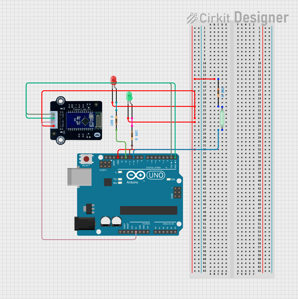
This circuit is designed to function as a security system using a Reed Switch to detect an open/close event, LEDs to indicate system status, a Bluetooth module for remote communication, and an Arduino UNO microcontroller to control the system logic. The system operates by monitoring the state of the Reed Switch. When the switch is activated, the system checks for a Bluetooth connection. If a correct passcode is received via Bluetooth, the green LED lights up; otherwise, the red LED is activated. If the Reed Switch is not activated and no Bluetooth connection is present, the system sends an intruder alert message.
Component List
Reed Switch
- A magnetic field sensor used to detect the presence of a magnetic field, typically used for security systems to monitor doors or windows.
Arduino UNO
- A microcontroller board based on the ATmega328P, with a variety of digital and analog I/O pins for interfacing with various sensors and actuators.
LED: Two Pin (red)
- A red light-emitting diode used to indicate an incorrect passcode or an alert condition.
LED: Two Pin (green)
- A green light-emitting diode used to indicate a correct passcode entry.
Resistor (200 Ohms)
- A resistor with a resistance of 200 Ohms, used to limit current to the red LED.
Resistor (100 Ohms)
- Two resistors each with a resistance of 100 Ohms, one used to limit current to the green LED, and the other for an unspecified purpose in the circuit.
MKE-M15 Bluetooth
- A Bluetooth module used for wireless communication with the security system, allowing for remote passcode entry and status updates.
Wiring Details
Reed Switch
- One pin connected to the Arduino UNO's digital pin D10.
- The other pin connected to a 200 Ohm resistor, which is then connected to the ground (GND).
Arduino UNO
- Digital pin D10 connected to the Reed Switch.
- Digital pin D12 connected to a 100 Ohm resistor leading to the green LED.
- Digital pin D11 connected to a 100 Ohm resistor leading to the red LED.
- Digital pins D0 (RX) and D1 (TX) connected to the Bluetooth module for serial communication.
- 5V and GND pins providing power to the Bluetooth module and common ground for the circuit.
LED: Two Pin (red)
- Cathode connected to the common ground through a 200 Ohm resistor.
- Anode connected to the Arduino UNO's digital pin D11 through a 100 Ohm resistor.
LED: Two Pin (green)
- Cathode connected to the common ground.
- Anode connected to the Arduino UNO's digital pin D12 through a 100 Ohm resistor.
Resistor (200 Ohms)
- One pin connected to the Reed Switch.
- The other pin connected to the common ground.
Resistor (100 Ohms)
- One resistor with one pin connected to the Arduino UNO's digital pin D12 and the other pin to the green LED.
- Another resistor with one pin connected to the Arduino UNO's digital pin D11 and the other pin to the red LED.
MKE-M15 Bluetooth
- RX pin connected to the Arduino UNO's digital pin D0 (TX).
- TX pin connected to the Arduino UNO's digital pin D1 (RX).
- 5V pin connected to the Arduino UNO's 5V power supply.
- GND pin connected to the common ground.
Documented Code
/*
 * Arduino Sketch for Security System
 *
 * This code controls a security system using a Reed Switch, LEDs, and a Bluetooth module.
 * When the Reed Switch is activated and the Bluetooth module is connected with the correct
 * passcode, the green LED will light up. If the passcode is incorrect, the red LED will light up.
 * If the Reed Switch is not activated and the Bluetooth module is not connected, an intruder
 * alert message will be sent to the operating software.
 */

#include <SoftwareSerial.h>

// Pin definitions
const int reedSwitchPin = 10;
const int greenLEDPin = 11;
const int redLEDPin = 12;
const int bluetoothRxPin = 0;
const int bluetoothTxPin = 1;

// Bluetooth setup
SoftwareSerial bluetooth(bluetoothRxPin, bluetoothTxPin);

void setup() {
  // Initialize serial communication
  Serial.begin(9600);
  bluetooth.begin(9600);

  // Initialize pin modes
  pinMode(reedSwitchPin, INPUT);
  pinMode(greenLEDPin, OUTPUT);
  pinMode(redLEDPin, OUTPUT);

  // Turn off LEDs initially
  digitalWrite(greenLEDPin, LOW);
  digitalWrite(redLEDPin, LOW);
}

void loop() {
  // Check the state of the Reed Switch
  int reedState = digitalRead(reedSwitchPin);

  // Check if Bluetooth is connected
  if (bluetooth.available()) {
    String passcode = bluetooth.readString();
    if (reedState == HIGH) {
      if (passcode == "correct_passcode") {
        // Correct passcode, light up green LED
        digitalWrite(greenLEDPin, HIGH);
        digitalWrite(redLEDPin, LOW);
      } else {
        // Incorrect passcode, light up red LED
        digitalWrite(greenLEDPin, LOW);
        digitalWrite(redLEDPin, HIGH);
      }
    }
  } else if (reedState == LOW) {
    // Reed Switch not activated and Bluetooth not connected
    Serial.println("Intruder alert!");
  }

  // Small delay to avoid bouncing
  delay(100);
}
This code is saved as sketch.ino and is intended to be uploaded to the Arduino UNO microcontroller. It includes the necessary setup for the pins, the main loop for checking the Reed Switch state, and the logic for handling Bluetooth communication and LED control.