ESP32-Controlled Lighting System with Pushbutton Activation and Relay Switching
Circuit Documentation
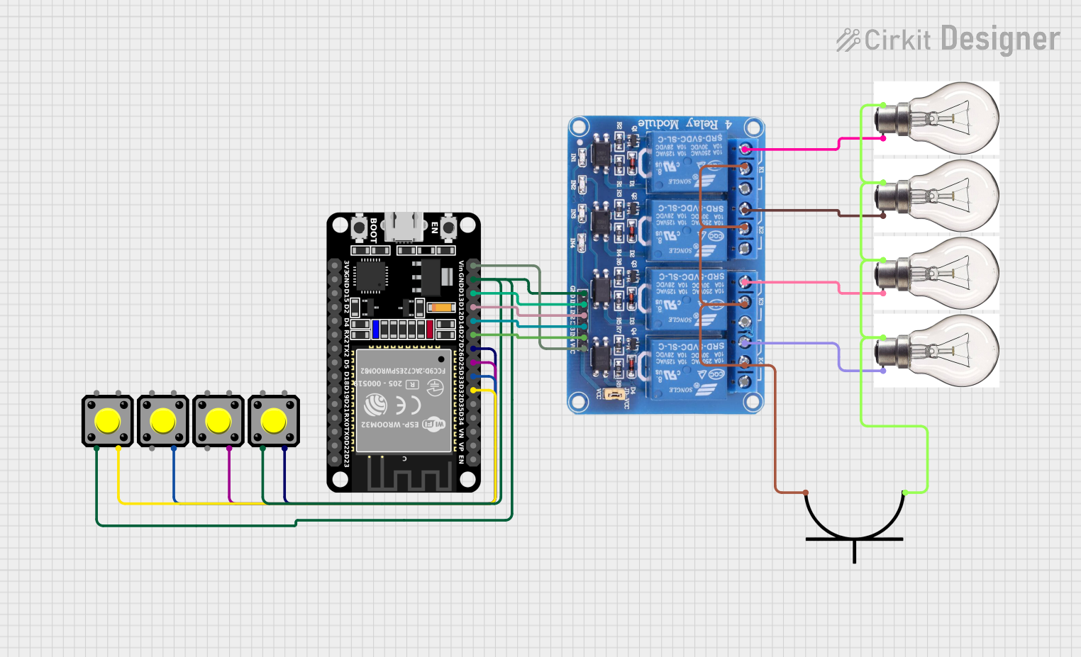
Summary of the Circuit
This circuit is designed to control a set of bulbs using an ESP32 microcontroller and a 4-channel relay module. The ESP32 reads the state of four pushbuttons and toggles the corresponding relay channels, which in turn control the power to the bulbs. The bulbs are connected to an AC power plug through the normally closed (NC) contacts of the relays, allowing the bulbs to be turned on or off based on the pushbutton inputs.
Component List
Pushbuttons
- Pushbutton: A momentary switch that, when pressed, creates a temporary electrical connection. Used to provide input to the microcontroller.
Bulbs
- Bulb: An electrical device that emits light when a current passes through it. In this circuit, multiple bulbs are used as the load controlled by the relay module.
AC Power Plug
- AC Power Plug: Provides the AC power source for the bulbs. It has a positive and a negative terminal for connecting to the relay module and bulbs.
ESP32 Microcontroller
- ESP32 (30 pin): A microcontroller with Wi-Fi and Bluetooth capabilities. It is used to read the state of the pushbuttons and control the relay module.
Relay Module
- Relay 4 Channel 5v: A module with four relays that can switch AC or DC loads. Each relay has a common (COM), normally open (NO), and normally closed (NC) contact.
Wiring Details
Pushbuttons
- Pushbutton 1: Connected to GPIO D25 of the ESP32.
- Pushbutton 2: Connected to GPIO D26 of the ESP32.
- Pushbutton 3: Connected to GPIO D33 of the ESP32.
- Pushbutton 4: Connected to GPIO D32 of the ESP32.
- All pushbuttons share a common ground connection with the ESP32 and the relay module.
Bulbs
- Bulb 1: Connected between the NC1 contact of the relay module and the positive terminal of the AC power plug.
- Bulb 2: Connected between the NC2 contact of the relay module and the positive terminal of the AC power plug.
- Bulb 3: Connected between the NC3 contact of the relay module and the positive terminal of the AC power plug.
- Bulb 4: Connected between the NC4 contact of the relay module and the positive terminal of the AC power plug.
- All bulbs share a common connection to the negative terminal of the AC power plug.
AC Power Plug
- Positive Terminal: Connected to the COM contacts of the relay module.
- Negative Terminal: Connected to the positive terminals of all bulbs.
ESP32 Microcontroller
- GPIO D25: Connected to Pushbutton 1.
- GPIO D26: Connected to Pushbutton 2.
- GPIO D33: Connected to Pushbutton 3.
- GPIO D32: Connected to Pushbutton 4.
- GPIO D13: Connected to IN1 of the relay module.
- GPIO D12: Connected to IN2 of the relay module.
- GPIO D14: Connected to IN3 of the relay module.
- GPIO D27: Connected to IN4 of the relay module.
- GND: Shared ground with pushbuttons and relay module.
- Vin: Connected to VCC of the relay module.
Relay Module
- IN1: Controlled by GPIO D13 of the ESP32.
- IN2: Controlled by GPIO D12 of the ESP32.
- IN3: Controlled by GPIO D14 of the ESP32.
- IN4: Controlled by GPIO D27 of the ESP32.
- VCC: Powered by Vin of the ESP32.
- GND: Shared ground with the ESP32 and pushbuttons.
- COM1-4: Connected to the positive terminal of the AC power plug.
- NC1-4: Connected to the negative terminals of bulbs 1-4 respectively.
Documented Code
// Define pin connections
const int button1Pin = 25; // Pushbutton 1 connected to GPIO 25
const int button2Pin = 26; // Pushbutton 2 connected to GPIO 26
const int button3Pin = 33; // Pushbutton 3 connected to GPIO 33
const int button4Pin = 32; // Pushbutton 4 connected to GPIO 32

const int relay1Pin = 13; // Relay 1 connected to GPIO 13
const int relay2Pin = 12; // Relay 2 connected to GPIO 12
const int relay3Pin = 14; // Relay 3 connected to GPIO 14
const int relay4Pin = 27; // Relay 4 connected to GPIO 27

// Variables to store button states
int button1State = 0;
int button2State = 0;
int button3State = 0;
int button4State = 0;

void setup() {
  // Initialize serial communication
  Serial.begin(115200);

  // Initialize button pins as input
  pinMode(button1Pin, INPUT);
  pinMode(button2Pin, INPUT);
  pinMode(button3Pin, INPUT);
  pinMode(button4Pin, INPUT);

  // Initialize relay pins as output
  pinMode(relay1Pin, OUTPUT);
  pinMode(relay2Pin, OUTPUT);
  pinMode(relay3Pin, OUTPUT);
  pinMode(relay4Pin, OUTPUT);

  // Set all relays to off initially
  digitalWrite(relay1Pin, LOW);
  digitalWrite(relay2Pin, LOW);
  digitalWrite(relay3Pin, LOW);
  digitalWrite(relay4Pin, LOW);
}

void loop() {
  // Read the state of each button
  button1State = digitalRead(button1Pin);
  button2State = digitalRead(button2Pin);
  button3State = digitalRead(button3Pin);
  button4State = digitalRead(button4Pin);

  // Control relay 1 based on button 1 state
  if (button1State == HIGH) {
    digitalWrite(relay1Pin, HIGH); // Turn on relay 1
  } else {
    digitalWrite(relay1Pin, LOW); // Turn off relay 1
  }

  // Control relay 2 based on button 2 state
  if (button2State == HIGH) {
    digitalWrite(relay2Pin, HIGH); // Turn on relay 2
  } else {
    digitalWrite(relay2Pin, LOW); // Turn off relay 2
  }

  // Control relay 3 based on button 3 state
  if (button3State == HIGH) {
    digitalWrite(relay3Pin, HIGH); // Turn on relay 3
  } else {
    digitalWrite(relay3Pin, LOW); // Turn off relay 3
  }

  // Control relay 4 based on button 4 state
  if (button4State == HIGH) {
    digitalWrite(relay4Pin, HIGH); // Turn on relay 4
  } else {
    digitalWrite(relay4Pin, LOW); // Turn off relay 4
  }

  // Add a small delay to debounce the buttons
  delay(50);
}
This code is responsible for reading the state of the pushbuttons and controlling the state of the relays accordingly. Each button press toggles the state of its corresponding relay, which in turn controls the power to the bulbs. The relays are initially set to off in the setup() function, and the loop() function continuously checks the state of each button to determine whether to turn the relays on or off. A small delay is added to debounce the buttons and prevent multiple toggles from a single press.