
Wi-Fi Controlled Motor and Water Pump System using ESP8266 and L9110
View and Edit Project In Cirkit Designer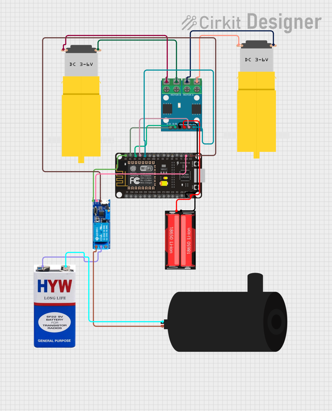
Circuit Documentation
Summary
This document provides a detailed overview of a circuit that includes an ESP8266 NodeMCU microcontroller, an L9110 motor driver, a relay module, a 9V battery, a 18650 Li-Ion battery, two hobby motors, and a water pump. The circuit is designed to control the motors and the water pump using the ESP8266 NodeMCU.
Component List
ESP8266 NodeMCU
- Description: A low-cost Wi-Fi microcontroller.
- Pins: D0, D1, D2, D3, D4, 3V3, GND, D5, D6, D7, D8, RX, TX, A0, RSV, SD3, SD2, SD1, CMD, SD0, CLK, EN, RST, VIN
L9110 Motor Driver
- Description: A dual-channel motor driver.
- Pins: MOTOR B-A, MOTOR B-B, MOTOR A-A, MOTOR A-B, B-IA, B-IB, GND, VCC, A-IA, A-IB
18650 Li-Ion Battery
- Description: A rechargeable lithium-ion battery.
- Pins: Positive, Negative
Hobby Motor (Motor amarillo motorreductor)
- Description: A small DC motor with a gearbox.
- Pins: vcc, GND
Relay Module (5V-30V)
- Description: A relay module for switching high-power devices.
- Pins: common contact, normally open, normally closed, trigger, V-, V+
9V Battery
- Description: A standard 9V battery.
- Pins: +, -
Water Pump
- Description: A small water pump.
- Pins: positive, negative
Wiring Details
ESP8266 NodeMCU
- D0 is connected to trigger of the Relay module.
- D1 is connected to B-IA of the L9110.
- D2 is connected to B-IB of the L9110.
- D3 is connected to A-IA of the L9110.
- D4 is connected to A-IB of the L9110.
- GND is connected to V- of the Relay module and GND of the L9110 and Negative of the 18650 Li-Ion.
- 3V3 is connected to V+ of the Relay module.
- VIN is connected to VCC of the L9110 and Positive of the 18650 Li-Ion.
L9110 Motor Driver
- MOTOR B-A is connected to vcc of the Hobby Motor.
- MOTOR B-B is connected to GND of the Hobby Motor.
- MOTOR A-A is connected to GND of the Hobby Motor.
- MOTOR A-B is connected to vcc of the Hobby Motor.
- B-IA is connected to D1 of the ESP8266 NodeMCU.
- B-IB is connected to D2 of the ESP8266 NodeMCU.
- A-IA is connected to D3 of the ESP8266 NodeMCU.
- A-IB is connected to D4 of the ESP8266 NodeMCU.
- GND is connected to GND of the ESP8266 NodeMCU and Negative of the 18650 Li-Ion.
- VCC is connected to VIN of the ESP8266 NodeMCU and Positive of the 18650 Li-Ion.
18650 Li-Ion Battery
- Positive is connected to VIN of the ESP8266 NodeMCU and VCC of the L9110.
- Negative is connected to GND of the ESP8266 NodeMCU and GND of the L9110.
Hobby Motor (Motor amarillo motorreductor)
- vcc is connected to MOTOR B-A of the L9110.
- GND is connected to MOTOR B-B of the L9110.
Hobby Motor (Motor amarillo motorreductor)
- vcc is connected to MOTOR A-B of the L9110.
- GND is connected to MOTOR A-A of the L9110.
Relay Module (5V-30V)
- common contact is connected to + of the 9V battery.
- normally open is connected to positive of the water pump.
- trigger is connected to D0 of the ESP8266 NodeMCU.
- V- is connected to GND of the ESP8266 NodeMCU.
- V+ is connected to 3V3 of the ESP8266 NodeMCU.
9V Battery
- + is connected to common contact of the Relay module.
- - is connected to negative of the water pump.
Water Pump
- positive is connected to normally open of the Relay module.
- negative is connected to - of the 9V battery.
Code
No code is provided for this circuit.
This document provides a comprehensive overview of the circuit, including a summary, component list, wiring details, and code documentation.