
Raspberry Pi 5-Based Obstacle-Avoiding Robot with Ultrasonic Sensors and DC Motors
View and Edit Project In Cirkit Designer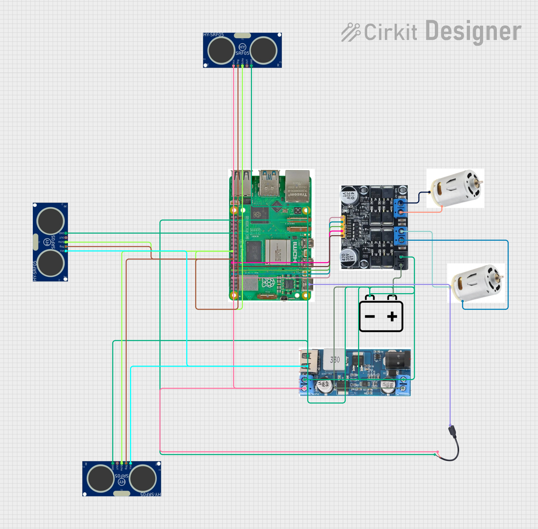
Circuit Documentation
Summary
This circuit is designed to control two DC motors using a Raspberry Pi 5 and a ZK-BM1 10A Motor Driver. Additionally, it includes three HC-SR05 ultrasonic sensors for distance measurement. The Raspberry Pi 5 is powered via a Micro USB to Cable (2 Pin) adapter, and the entire system is powered by a 12V battery with a DCDC 12V/5V 3A converter to provide the necessary 5V for the sensors and Raspberry Pi.
Component List
Raspberry Pi 5
- Description: A single-board computer used for controlling the motor driver and reading sensor data.
- Pins: Type-C, Micro HDMI 1, Micro HDMI 2, Camera 1, Camera 2, PoE, Fan, PCIe, USB 3.0, USB 2.0, Ethernet, 5V, GND, 3.3v, GPIO 14, GPIO 15, GPIO 18, GPIO 23, GPIO 24, GPIO 25, GPIO 8, GPIO 7, GPIO 1, GPIO 12, GPIO 16, GPIO 20, GPIO 21, GPIO 2, GPIO 3, GPIO 4, GPIO 17, GPIO 27, GPIO 22, GPIO 10, GPIO 9, GPIO 11, GPIO 0, GPIO 5, GPIO 6, GPIO 13, GPIO 19, GPIO 26
DC Motor RC 7.4V
- Description: A DC motor used for driving the system.
- Pins: Negative, Positive
ZK-BM1 10A Motor Driver
- Description: A motor driver used to control the DC motors.
- Pins: B+, B-, M1A, M1B, M2A, M2B, IN1, IN2, IN3, IN4, GND
12V Battery
- Description: A power source for the circuit.
- Pins: -, +
DCDC 12V/5V 3A
- Description: A DC-DC converter to step down 12V to 5V.
- Pins: 12V (+), GND, 5V (+), Vin (+), V in (-)
Micro USB to Cable (2 Pin)
- Description: A cable to power the Raspberry Pi.
- Pins: Micro USB, +, -
HC-SR05
- Description: An ultrasonic sensor for distance measurement.
- Pins: VCC, TRIG, GND, ECHO, OUT
Wiring Details
Raspberry Pi 5
- Type-C connected to Micro USB of Micro USB to Cable (2 Pin)
- GPIO 14 connected to IN1 of ZK-BM1 10A Motor Driver
- GPIO 15 connected to IN2 of ZK-BM1 10A Motor Driver
- GPIO 18 connected to IN3 of ZK-BM1 10A Motor Driver
- GPIO 23 connected to IN4 of ZK-BM1 10A Motor Driver
- GPIO 24 connected to TRIG of all HC-SR05 sensors
- GPIO 25 connected to ECHO of all HC-SR05 sensors
- GND connected to GND of ZK-BM1 10A Motor Driver
DC Motor RC 7.4V
Negative connected to M2B of ZK-BM1 10A Motor Driver
Positive connected to M2A of ZK-BM1 10A Motor Driver
Negative connected to M1B of ZK-BM1 10A Motor Driver
Positive connected to M1A of ZK-BM1 10A Motor Driver
ZK-BM1 10A Motor Driver
- B+ connected to Vin (+) of DCDC 12V/5V 3A
- B- connected to GND of DCDC 12V/5V 3A
- GND connected to GND of Raspberry Pi 5
12V Battery
- + connected to Vin (+) of DCDC 12V/5V 3A
- - connected to GND of DCDC 12V/5V 3A
DCDC 12V/5V 3A
- Vin (+) connected to + of 12V Battery
- V in (-) connected to - of 12V Battery
- 5V (+) connected to + of Micro USB to Cable (2 Pin)
- GND connected to - of Micro USB to Cable (2 Pin)
- 5V (+) connected to VCC of all HC-SR05 sensors
- GND connected to GND of all HC-SR05 sensors
Micro USB to Cable (2 Pin)
- Micro USB connected to Type-C of Raspberry Pi 5
- + connected to 5V (+) of DCDC 12V/5V 3A
- - connected to GND of DCDC 12V/5V 3A
HC-SR05
- TRIG connected to GPIO 24 of Raspberry Pi 5
- ECHO connected to GPIO 25 of Raspberry Pi 5
- VCC connected to 5V (+) of DCDC 12V/5V 3A
- GND connected to GND of DCDC 12V/5V 3A
Code Documentation
const int IN1 = 14;
const int IN2 = 15;
const int IN3 = 18;
const int IN4 = 23;
const int TRIG = 24;
const int ECHO = 25;

void setup()
{
  pinMode(IN1, OUTPUT);
  pinMode(IN2, OUTPUT);
  pinMode(IN3, OUTPUT);
  pinMode(IN4, OUTPUT);
  pinMode(TRIG, OUTPUT);
  pinMode(ECHO, INPUT);

  Serial.begin(9600);
}

void loop()
{
  long duration, distance;
  digitalWrite(TRIG, LOW);
  delayMicroseconds(2);
  digitalWrite(TRIG, HIGH);
  delayMicroseconds(10);
  digitalWrite(TRIG, LOW);
  duration = pulseIn(ECHO, HIGH);
  distance = (duration / 2) / 29.1;
  Serial.print("Distance:10");
  Serial.print(distance);
  Serial.println("10cm");
  if (distance < 10)
  {
    digitalWrite(IN1, LOW);
    digitalWrite(IN2, LOW);
    digitalWrite(IN3, LOW);
    digitalWrite(IN4, LOW);
  }
   else
   {
    digitalWrite(IN1, HIGH);
    digitalWrite(IN2, LOW);
    digitalWrite(IN3, HIGH);
    digitalWrite(IN4, LOW);
  }

  delay(100);
}
Code Explanation
- Pin Definitions: The GPIO pins for motor control and sensor connections are defined.
- Setup Function: Initializes the GPIO pins and starts the serial communication.
- Loop Function: Measures the distance using the HC-SR05 sensor. If the distance is less than 10 cm, it stops the motors; otherwise, it runs the motors. The distance is also printed to the serial monitor.