
Arduino Mega 2560-Based Real-Time Clock and Data Logging System with OLED Display
View and Edit Project In Cirkit Designer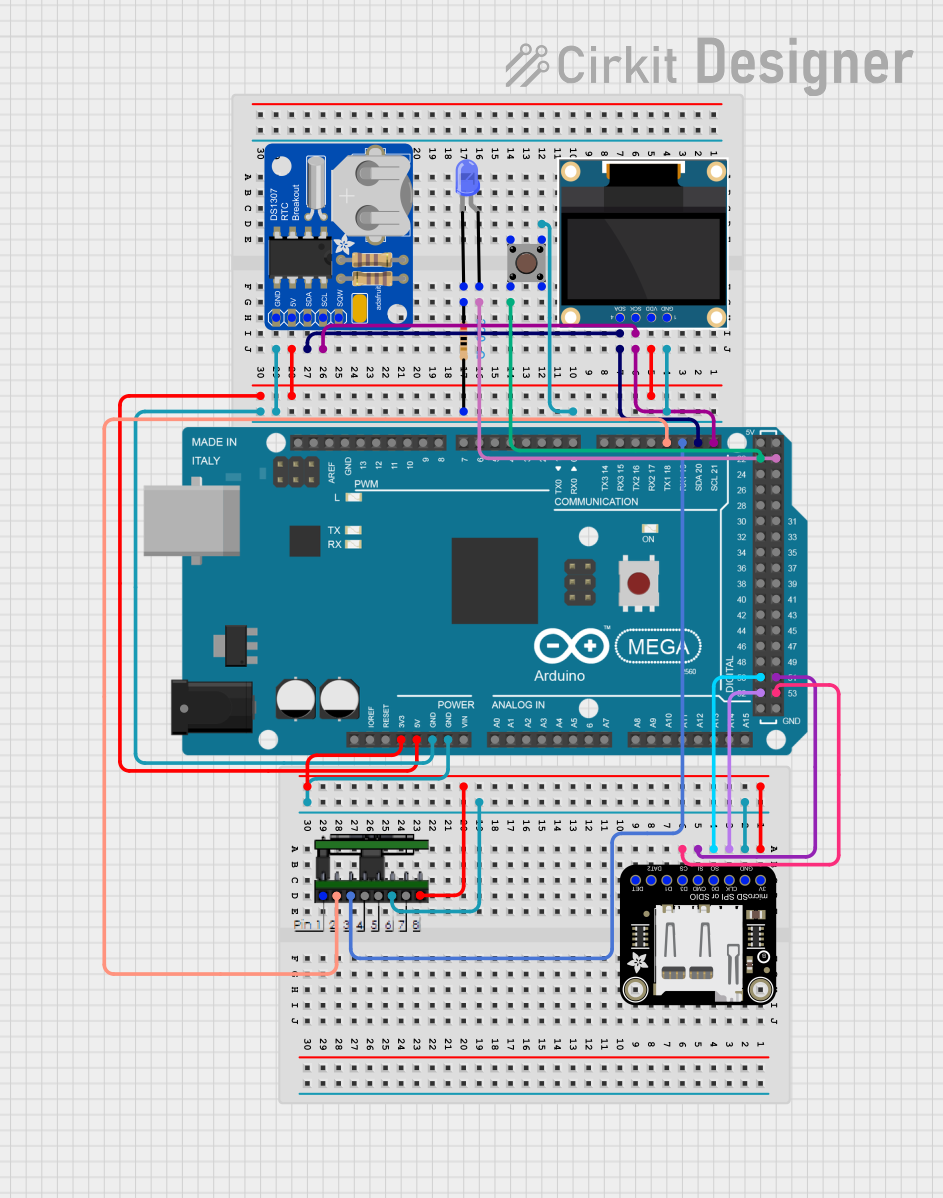
Circuit Documentation
Summary
This circuit involves an Arduino Mega 2560 microcontroller interfacing with various components including an OLED display, an RTC module, an SD card breakout, a pushbutton, and an LED. The circuit is designed to demonstrate basic interfacing and control of these components using the Arduino platform.
Component List
Arduino Mega 2560
- Description: A microcontroller board based on the ATmega2560.
- Pins: IOREF, RESET, 3V3, 5V, GND, VIN, A0-A15, D21/SCL, D20/SDA, D19/RX1, D18/TX1, D17 PWM/RX2, D16 PWM/TX2, D15/RX3, D14/TX3, D0 RX0, D1 TX0, D2 PWM, D3 PWM, D4 PWM, D5 PWM, D6 PWM, D7 PWM, D8 PWM, D9 PWM, D10 PWM, D11 PWM, D12 PWM, D13 PWM, AREF, SDA, SCL, D52, D50, D48, D46, D44, D42, D40, D38, D36, D34, D32, D30, D28, D26, D24, D22, D53, D51, D49, D47, D45, D43, D41, D39, D37, D35, D33, D31, D29, D27, D25, D23, 6swdw.
Adafruit DS1307 RTC Breakout
- Description: A real-time clock module.
- Pins: SQW, SCL, SDA, VCC, GND.
LED: Two Pin (blue)
- Description: A blue LED with two pins.
- Pins: Cathode, Anode.
Adafruit SDIO microSD Breakout
- Description: A microSD card breakout board.
- Pins: 3.3V, GND, SCLK, DO, DI, CS, DAT1, DAT2, CARDDET.
Pushbutton
- Description: A simple pushbutton switch.
- Pins: Pin 3 (out), Pin 4 (out), Pin 1 (in), Pin 2 (in).
0.96" OLED
- Description: A small OLED display.
- Pins: GND, VDD, SCK, SDA.
DGS
- Description: A generic component placeholder.
- Pins: None specified.
Resistor
- Description: A resistor with a resistance of 220 Ohms.
- Pins: Pin1, Pin2.
Wiring Details
Arduino Mega 2560
GND is connected to:
- GND of 0.96" OLED
- Pin 2 of Resistor
- Pin 3 (out) of Pushbutton
- GND of Adafruit DS1307 RTC Breakout
- GND of Adafruit SDIO microSD Breakout
- DGS
5V is connected to:
- VDD of 0.96" OLED
- VCC of Adafruit DS1307 RTC Breakout
D21/SCL is connected to:
- SCL of Adafruit DS1307 RTC Breakout
- SCK of 0.96" OLED
D20/SDA is connected to:
- SDA of Adafruit DS1307 RTC Breakout
- SDA of 0.96" OLED
D22 is connected to:
- Pin 2 (in) of Pushbutton
D23 is connected to:
- Anode of LED: Two Pin (blue)
3V3 is connected to:
- 3.3V of Adafruit SDIO microSD Breakout
- DGS
D52 is connected to:
- SCLK of Adafruit SDIO microSD Breakout
D50 is connected to:
- DO of Adafruit SDIO microSD Breakout
D51 is connected to:
- DI of Adafruit SDIO microSD Breakout
D53 is connected to:
- CS of Adafruit SDIO microSD Breakout
D19/RX1 is connected to:
- DGS
D18/TX1 is connected to:
- DGS
Adafruit DS1307 RTC Breakout
GND is connected to:
- GND of Arduino Mega 2560
VCC is connected to:
- 5V of Arduino Mega 2560
SCL is connected to:
- D21/SCL of Arduino Mega 2560
- SCK of 0.96" OLED
SDA is connected to:
- D20/SDA of Arduino Mega 2560
- SDA of 0.96" OLED
LED: Two Pin (blue)
Anode is connected to:
- D23 of Arduino Mega 2560
Cathode is connected to:
- Pin1 of Resistor
Adafruit SDIO microSD Breakout
3.3V is connected to:
- 3V3 of Arduino Mega 2560
- DGS
GND is connected to:
- GND of Arduino Mega 2560
- DGS
SCLK is connected to:
- D52 of Arduino Mega 2560
DO is connected to:
- D50 of Arduino Mega 2560
DI is connected to:
- D51 of Arduino Mega 2560
CS is connected to:
- D53 of Arduino Mega 2560
Pushbutton
Pin 3 (out) is connected to:
- GND of Arduino Mega 2560
Pin 2 (in) is connected to:
- D22 of Arduino Mega 2560
0.96" OLED
GND is connected to:
- GND of Arduino Mega 2560
VDD is connected to:
- 5V of Arduino Mega 2560
SCK is connected to:
- D21/SCL of Arduino Mega 2560
- SCL of Adafruit DS1307 RTC Breakout
SDA is connected to:
- D20/SDA of Arduino Mega 2560
- SDA of Adafruit DS1307 RTC Breakout
Resistor
Pin1 is connected to:
- Cathode of LED: Two Pin (blue)
Pin2 is connected to:
- GND of Arduino Mega 2560
DGS
- Pin is connected to:
- 3V3 of Arduino Mega 2560
- GND of Arduino Mega 2560
- D19/RX1 of Arduino Mega 2560
- D18/TX1 of Arduino Mega 2560
Documented Code
Arduino Mega 2560 Code
void setup() {
  // put your setup code here, to run once:

}

void loop() {
  // put your main code here, to run repeatedly:

}
This code is a basic template for the Arduino Mega 2560. The setup() function is where you initialize your components and settings, and the loop() function is where you place the main code that runs repeatedly.