
Arduino UNO-Based Wi-Fi Environmental Monitoring System with Alerts
View and Edit Project In Cirkit Designer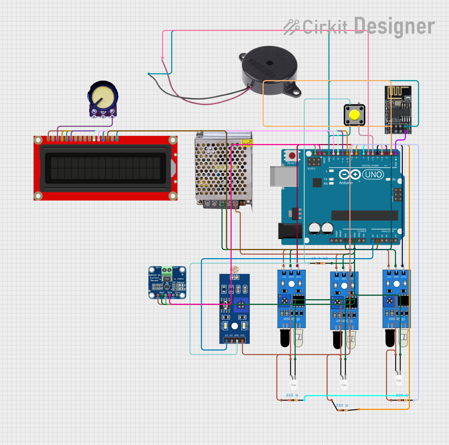
Circuit Documentation
Summary
This circuit integrates a variety of components including an Arduino UNO, multiple IR sensors, LEDs, an LDR (Light Dependent Resistor), a pushbutton, a buzzer, an INA219 current sensor, an ESP8266-01 WiFi module, a power supply, resistors, an LCD screen, and a potentiometer. The Arduino UNO serves as the central microcontroller, interfacing with sensors, input/output devices, and communication modules to perform the circuit's intended functions. The circuit is designed to interact with the environment through sensors, display information on an LCD screen, and communicate wirelessly via the ESP8266-01 module.
Component List
- Arduino UNO: A microcontroller board based on the ATmega328P, featuring digital and analog I/O pins.
- IR Sensors: Used to detect objects within a certain range by emitting and receiving infrared light.
- LDR: A light-sensitive device that changes resistance based on light intensity.
- Pushbutton: A simple switch mechanism for controlling some aspect of a machine or a process.
- LEDs (White): Light Emitting Diodes used as indicators or for illumination.
- WiFi Module ESP8266-01: A self-contained SOC with integrated TCP/IP protocol stack that can give access to WiFi networks.
- Power Supply 5V 5A: Provides a stable 5V DC power supply for the circuit.
- Resistors: Passive electrical components that provide resistance in the electrical circuit.
- INA219: A current sensor that can measure voltage, current, and power of a load.
- Buzzer: An audio signaling device that can be used to alert users or provide feedback.
- LCD Screen: A display module for showing text or graphics.
- Potentiometer: A three-terminal resistor with a sliding or rotating contact that forms an adjustable voltage divider.
Wiring Details
Arduino UNO
- 3.3V connected to ESP8266-01 (+3V3)
- 5V connected to multiple components including resistors, LCD screen (VSS), and IR sensors (VCC)
- GND connected to various components' ground pins, including IR sensors (GND), INA219 (GND), and the power supply (GND)
- A0 connected to LDR (A0) and LCD screen (D6)
- A1 connected to LCD screen (D7)
- SCL connected to INA219 (SCL)
- SDA connected to INA219 (SDA)
- D13 connected to LCD screen (D5)
- D12 connected to LCD screen (D4)
- D11 connected to LCD screen (E)
- D10 connected to LCD screen (RS)
- D9 connected to a resistor (pin2)
- D8 connected to a resistor (pin2)
- D7 connected to a resistor (pin2)
- D6 connected to Buzzer (POSITIVE)
- D5 connected to Pushbutton (Pin 3)
- D4 connected to IR sensor (out)
- D3 connected to IR sensor (out)
- D2 connected to IR sensor (out)
- D1 connected to ESP8266-01 (RX)
- D0 connected to ESP8266-01 (TX)
IR Sensors
- out connected to Arduino UNO (D2, D3, D4)
- gnd connected to Arduino UNO (GND)
- vcc connected to Arduino UNO (5V)
LDR
- A0 connected to Arduino UNO (A0)
- D0 not connected
- GND connected to Pushbutton (Pin 1) and Resistor (pin1)
- VCC connected to Arduino UNO (5V)
Pushbutton
- Pin 2 connected to Arduino UNO (GND)
- Pin 1 connected to LDR (GND) and Resistor (pin1)
- Pin 3 connected to Arduino UNO (D5)
- Pin 4 not connected
LEDs (White)
- cathode connected to Arduino UNO (GND)
- anode connected to Arduino UNO (5V) through a resistor (pin2)
WiFi Module ESP8266-01
- RX connected to Arduino UNO (D1)
- GPIO0 not connected
- GPIO2 not connected
- GND connected to Arduino UNO (GND)
- +3V3 connected to Arduino UNO (3.3V)
- Reset not connected
- CH-PD Chip power down not connected
- TX connected to Arduino UNO (D0)
Power Supply 5V 5A
- 220V Positive Pole (AC) not connected
- 220V Negative Pole (AC) not connected
- GND connected to Arduino UNO (GND)
- GND (DC) not connected
- 12V-24V Output (DC) connected to Arduino UNO (5V)
Resistors
- pin1 connected to Arduino UNO (5V) or Pushbutton (Pin 1)
- pin2 connected to Arduino UNO (GND) or LEDs (anode)
INA219
- VCC connected to Arduino UNO (5V)
- GND connected to Arduino UNO (GND)
- SCL connected to Arduino UNO (SCL)
- SDA connected to Arduino UNO (SDA)
- VIN - not connected
- VIN + not connected
Buzzer
- POSITIVE connected to Arduino UNO (D6)
- NEGATIVE connected to Arduino UNO (GND)
LCD Screen
- Backlight (GND) connected to Arduino UNO (GND)
- VSS connected to Arduino UNO (5V)
- VDD not connected
- Contrast connected to Potentiometer (VCC)
- RS connected to Arduino UNO (D10)
- E connected to Arduino UNO (D11)
- R/W connected to Arduino UNO (GND)
- D0-D7 connected to Arduino UNO (A0, A1, D13, D12, D11, D10)
Potentiometer
- GND not connected
- Output not connected
- VCC connected to LCD screen (Contrast)
Documented Code
void setup() {
  // put your setup code here, to run once:

}

void loop() {
  // put your main code here, to run repeatedly:

}
The provided code is a template for an Arduino sketch with empty setup() and loop() functions. The setup() function is intended to contain initialization code that runs once when the program starts, such as pin mode declarations. The loop() function is for code that runs continuously, containing the main logic of the program. This code needs to be populated with specific instructions to control and interact with the connected hardware as per the circuit's design and requirements.