
Arduino UNO R4 WiFi Fire Detection System with Solar Power and Buzzer Alert
View and Edit Project In Cirkit Designer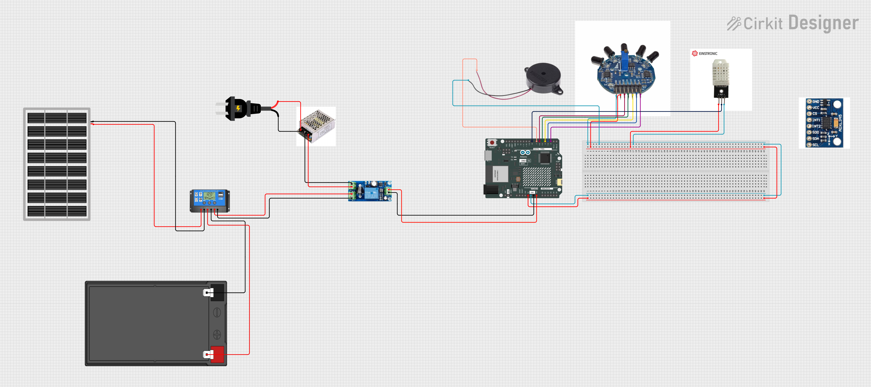
Circuit Documentation
Summary
The circuit is designed to monitor for the presence of flames using an array of IR Flame sensors interfaced with an Arduino UNO R4 WiFi microcontroller. When a flame is detected by any of the sensors, a buzzer is activated to alert the presence of fire. The system is powered by a UPS module, which is charged by a solar panel through a solar charge controller. The UPS module also provides power to an inverter connected to an AC source for additional power requirements.
Component List
Arduino UNO R4 WiFi
- Microcontroller board based on the ATmega328P
- WiFi capabilities for IoT applications
- Digital I/O Pins: 14 (of which 6 provide PWM output)
- Analog Input Pins: 6
IR FLAME
- Flame sensor module capable of detecting fire source or other light sources of the wavelength in the range of 760nm - 1100 nm
Buzzer
- An electromechanical component that produces sound when energized
DHT22
- Digital temperature and humidity sensor with a calibrated digital signal output
ADXL345
- A small, thin, low power, 3-axis accelerometer with high resolution (13-bit) measurement
Solar Panel
- Photovoltaic panel designed to absorb the sun's rays as a source of energy for generating electricity
Solar Charge Controller
- A device that controls the power going from the solar panels to the battery and protects against overcharging
12v 7ah Battery
- A rechargeable battery providing a nominal 12V voltage and 7Ah capacity
UPS Module
- Uninterruptible power supply module that provides backup power when the input power source fails
AC Source
- An alternating current (AC) power source
Inverter
- A power electronic device or circuitry that changes direct current (DC) to alternating current (AC)
Wiring Details
Arduino UNO R4 WiFi
5Vconnected to IR FLAME VCC, DHT22 VCCGNDconnected to IR FLAME GND, Buzzer NEGATIVE, DHT22 GND, UPS Module OUT-VINconnected to UPS Module OUT+- Digital pins
D2toD6connected to corresponding IR FLAME pinsD1A1toD5A5 D7connected to Buzzer POSITIVED8connected to DHT22 OUT
IR FLAME
VCCconnected to Arduino UNO R4 WiFi 5VGNDconnected to Arduino UNO R4 WiFi GNDD1A1toD5A5connected to corresponding Arduino UNO R4 WiFi digital pinsD2toD6
Buzzer
POSITIVEconnected to Arduino UNO R4 WiFi D7NEGATIVEconnected to Arduino UNO R4 WiFi GND
DHT22
VCCconnected to Arduino UNO R4 WiFi 5VOUTconnected to Arduino UNO R4 WiFi D8GNDconnected to Arduino UNO R4 WiFi GND
Solar Panel
vccconnected to Solar Charge Controller Solar Cell +gndconnected to Solar Charge Controller Solar Cell -
Solar Charge Controller
Solar Cell +andSolar Cell -connected to corresponding Solar Panel pinsBattery +andBattery -connected to corresponding 12v 7ah Battery pinsLoad +andLoad -connected to UPS Module BAT+ and BAT-
12v 7ah Battery
12v +connected to Solar Charge Controller Battery +12v -connected to Solar Charge Controller Battery -
UPS Module
BAT+andBAT-connected to Solar Charge Controller Load + and Load -OUT+connected to Arduino UNO R4 WiFi VINOUT-connected to Arduino UNO R4 WiFi GNDDC+andDC-connected to corresponding Inverter pins P and N
Inverter
PandNconnected to corresponding UPS Module pins DC+ and DC-LandNconnected to corresponding AC Source pins + and -
AC Source
+and-connected to corresponding Inverter pins L and N
Documented Code
#define FLAME_SENSOR_PIN1 2  // D1A1
#define FLAME_SENSOR_PIN2 3  // D2A2
#define FLAME_SENSOR_PIN3 4  // D3A3
#define FLAME_SENSOR_PIN4 5  // D4A4
#define FLAME_SENSOR_PIN5 6  // D5A5
#define BUZZER_PIN 7         // Buzzer pin

void setup() {
  pinMode(FLAME_SENSOR_PIN1, INPUT);
  pinMode(FLAME_SENSOR_PIN2, INPUT);
  pinMode(FLAME_SENSOR_PIN3, INPUT);
  pinMode(FLAME_SENSOR_PIN4, INPUT);
  pinMode(FLAME_SENSOR_PIN5, INPUT);
  pinMode(BUZZER_PIN, OUTPUT);

  Serial.begin(9600);
}

void loop() {
  if (digitalRead(FLAME_SENSOR_PIN1) == LOW ||
      digitalRead(FLAME_SENSOR_PIN2) == LOW ||
      digitalRead(FLAME_SENSOR_PIN3) == LOW ||
      digitalRead(FLAME_SENSOR_PIN4) == LOW ||
      digitalRead(FLAME_SENSOR_PIN5) == LOW) {

    Serial.println("Fire detected!");
    digitalWrite(BUZZER_PIN, HIGH); // Turn on the buzzer
    delay(200);                     // Delay to keep the buzzer on briefly
    digitalWrite(BUZZER_PIN, LOW);  // Turn off the buzzer
  } else {
    Serial.println("No fire detected.");
    digitalWrite(BUZZER_PIN, LOW);  // Ensure buzzer is off
  }

  delay(500); // Adjust delay as needed
}
This code is designed to run on the Arduino UNO R4 WiFi microcontroller. It initializes the flame sensor pins and the buzzer pin, then continuously checks the flame sensor pins for a LOW signal, indicating the detection of a flame. If a flame is detected, it activates the buzzer and prints a message to the serial monitor. If no flame is detected, it ensures the buzzer is off and prints a different message to the serial monitor.