
Circuit Documentation
Summary
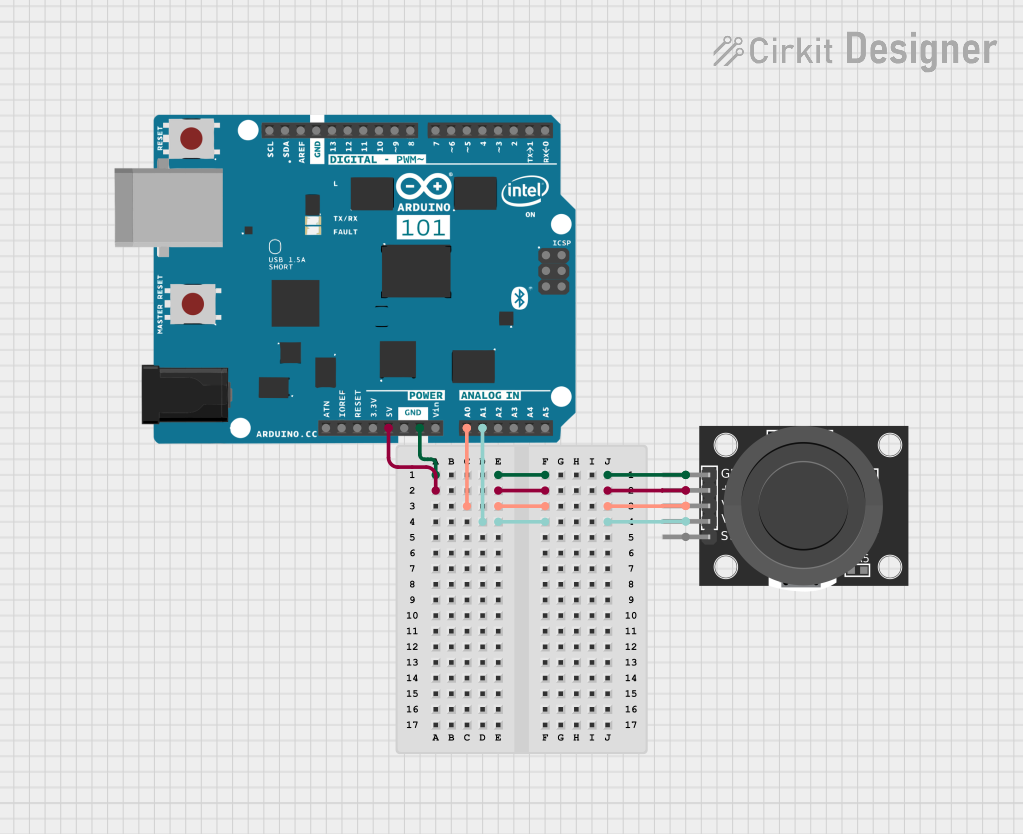
This document provides a detailed overview of a circuit that includes a KY-023 Dual Axis Joystick Module and an Arduino 101 microcontroller. The joystick module is connected to the Arduino to provide analog input for both the X and Y axes, as well as a digital input for the joystick button.
Component List
KY-023 Dual Axis Joystick Module
- Description: A joystick module that provides two analog outputs corresponding to the X and Y axes and a digital output for the joystick button.
- Pins: GND, +5V, VRx, VRy, SW
Arduino 101
- Description: A microcontroller board based on the Intel Curie module. It features analog and digital I/O pins, PWM outputs, and communication interfaces.
- Pins: A5/SCL, A4/SDA, AREF, GND, D13/SCK, D12/MISO, D11 PWM/MOSI, D10 PWM/SS, D9 PWM, D8, D7, D6 PWM, D5 PWM, D4, D3 PWM, D2, D1/TX, D0/RX, AIN, ioref, RESET, 3V3, 5V, VIN, A0, A1, A2, A3, ICSP MISO, ICSP SCK, ICSP MOSI
Wiring Details
KY-023 Dual Axis Joystick Module
- GND: Connected to Arduino 101 GND
- +5V: Connected to Arduino 101 5V
- VRx: Connected to Arduino 101 A0
- VRy: Connected to Arduino 101 A1
- SW: Not connected
Arduino 101
- GND: Connected to KY-023 Dual Axis Joystick Module GND
- 5V: Connected to KY-023 Dual Axis Joystick Module +5V
- A0: Connected to KY-023 Dual Axis Joystick Module VRx
- A1: Connected to KY-023 Dual Axis Joystick Module VRy
Code
No code is provided for this circuit.
This document provides a comprehensive overview of the components and their connections in the circuit. The KY-023 Dual Axis Joystick Module is interfaced with the Arduino 101 to provide analog inputs for the X and Y axes. The wiring details ensure proper connections between the components.