
Arduino-Based Bluetooth-Controlled Servo System with Flex Sensors and MPU-6050
View and Edit Project In Cirkit Designer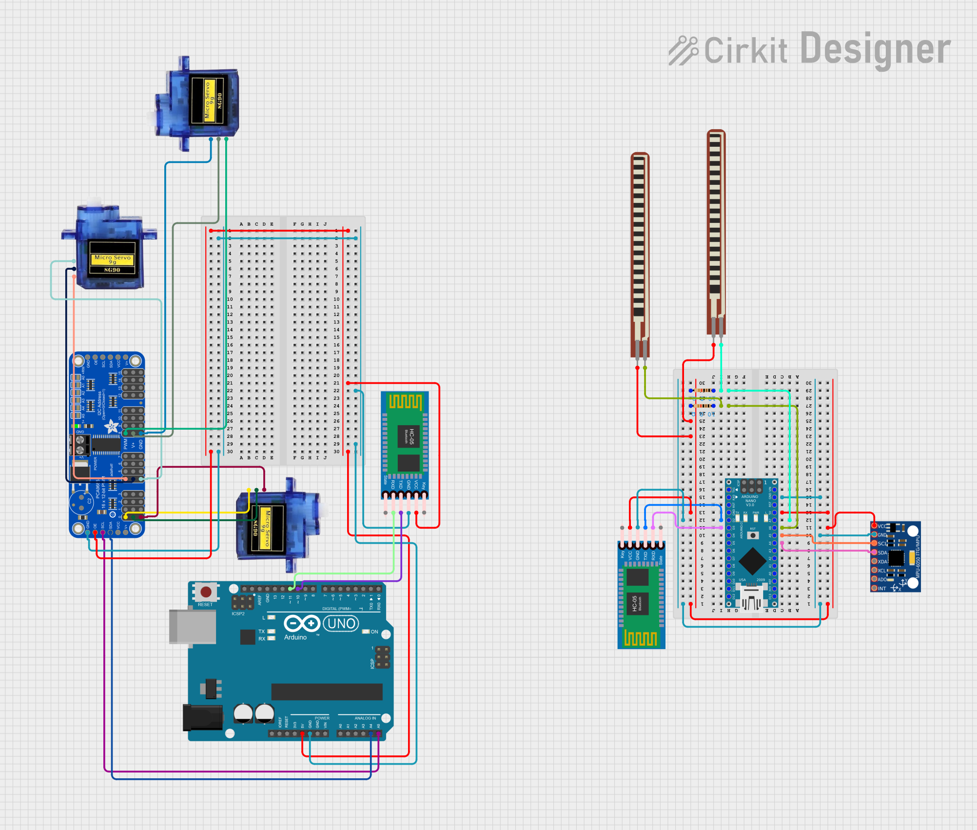
Circuit Documentation
Summary
This circuit involves an Arduino UNO and an Arduino Nano, both of which are used to control various components including servos, a Bluetooth module, and sensors. The Arduino UNO is connected to a PCA9685 PWM Servo Breakout to control multiple servos, while the Arduino Nano reads data from flex sensors and an MPU-6050 accelerometer and communicates this data via a Bluetooth module.
Component List
Micro servo 9G
- Description: Small servo motor used for precise control of angular position.
- Pins: GND, +5V, PWM
Arduino UNO
- Description: Microcontroller board based on the ATmega328P.
- Pins: UNUSED, IOREF, Reset, 3.3V, 5V, GND, Vin, A0, A1, A2, A3, A4, A5, SCL, SDA, AREF, D13, D12, D11, D10, D9, D8, D7, D6, D5, D4, D3, D2, D1, D0
Adafruit PCA9685 PWM Servo Breakout
- Description: 16-channel, 12-bit PWM driver.
- Pins: 5.0V, GND, PWRIN, PWM7, PWM6, PWM5, PWM4, PWM3, PWM2, PWM1, PWM0, VCC, SDA, SCL, OE, PWM15, PWM14, PWM13, PWM12, PWM11, PWM10, PWM9, PWM8
Arduino Nano
- Description: Small, complete, and breadboard-friendly board based on the ATmega328P.
- Pins: D1/TX, D0/RX, RESET, GND, D2, D3, D4, D5, D6, D7, D8, D9, D10, D11/MOSI, D12/MISO, VIN, 5V, A7, A6, A5, A4, A3, A2, A1, A0, AREF, 3V3, D13/SCK
HC-05 Bluetooth Module
- Description: Bluetooth module for wireless communication.
- Pins: Key, VCC, TXD, RXD, State, GND
2.2 inch Basic Flex Resistor
- Description: Flex sensor used to measure bending or flexing.
- Pins: Pin 2, pin 1
Resistor
- Description: Electrical component that limits or regulates the flow of electrical current.
- Pins: pin1, pin2
- Properties: Resistance: 10 Ohms
MPU-6050
- Description: 6-axis motion tracking device that combines a 3-axis gyroscope and a 3-axis accelerometer.
- Pins: VCC, GND, SCL, SDA, XDA, XCL, AD0, INT
Wiring Details
Micro servo 9G
- GND connected to GND of Adafruit PCA9685 PWM Servo Breakout
- +5V connected to 5.0V of Adafruit PCA9685 PWM Servo Breakout
- PWM connected to PWM4 of Adafruit PCA9685 PWM Servo Breakout
Micro servo 9G
- GND connected to GND of Adafruit PCA9685 PWM Servo Breakout
- +5V connected to 5.0V of Adafruit PCA9685 PWM Servo Breakout
- PWM connected to PWM0 of Adafruit PCA9685 PWM Servo Breakout
Micro servo 9G
- GND connected to GND of Adafruit PCA9685 PWM Servo Breakout
- +5V connected to 5.0V of Adafruit PCA9685 PWM Servo Breakout
- PWM connected to PWM8 of Adafruit PCA9685 PWM Servo Breakout
Arduino UNO
- 5V connected to VCC of HC-05 Bluetooth Module
- GND connected to GND of HC-05 Bluetooth Module
- D10 connected to TXD of HC-05 Bluetooth Module
- D11 connected to RXD of HC-05 Bluetooth Module
- A4 connected to SDA of Adafruit PCA9685 PWM Servo Breakout
- A5 connected to SCL of Adafruit PCA9685 PWM Servo Breakout
Adafruit PCA9685 PWM Servo Breakout
- 5.0V connected to +5V of Micro servo 9G
- GND connected to GND of Micro servo 9G
- PWM4 connected to PWM of Micro servo 9G
- PWM0 connected to PWM of Micro servo 9G
- PWM8 connected to PWM of Micro servo 9G
- SDA connected to A4 of Arduino UNO
- SCL connected to A5 of Arduino UNO
Arduino Nano
- A4 connected to SDA of MPU-6050
- A5 connected to SCL of MPU-6050
- A6 connected to pin1 of Resistor and pin 1 of 2.2 inch Basic Flex Resistor
- A7 connected to pin1 of Resistor and pin 1 of 2.2 inch Basic Flex Resistor
- D2 connected to TXD of HC-05 Bluetooth Module
- D3 connected to RXD of HC-05 Bluetooth Module
- 5V connected to pin2 of Resistor, VCC of MPU-6050, VCC of HC-05 Bluetooth Module, and Pin 2 of 2.2 inch Basic Flex Resistor
- GND connected to GND of MPU-6050 and GND of HC-05 Bluetooth Module
HC-05 Bluetooth Module
- VCC connected to 5V of Arduino Nano
- GND connected to GND of Arduino Nano
- TXD connected to D2 of Arduino Nano
- RXD connected to D3 of Arduino Nano
2.2 inch Basic Flex Resistor
- Pin 2 connected to 5V of Arduino Nano
- pin 1 connected to pin1 of Resistor and A6 of Arduino Nano
2.2 inch Basic Flex Resistor
- Pin 2 connected to 5V of Arduino Nano
- pin 1 connected to pin1 of Resistor and A7 of Arduino Nano
Resistor
- pin1 connected to pin 1 of 2.2 inch Basic Flex Resistor and A6 of Arduino Nano
- pin2 connected to 5V of Arduino Nano
Resistor
- pin1 connected to pin 1 of 2.2 inch Basic Flex Resistor and A7 of Arduino Nano
- pin2 connected to 5V of Arduino Nano
MPU-6050
- VCC connected to 5V of Arduino Nano
- GND connected to GND of Arduino Nano
- SDA connected to A4 of Arduino Nano
- SCL connected to A5 of Arduino Nano
Code Documentation
Arduino UNO Sketch
/*
 * Arduino UNO Sketch
 * This code controls three servos connected via a PCA9685 PWM driver.
 * The servos are connected to PWM channels 0, 4, and 8 of the PCA9685.
 * The servos will move slowly back and forth.
 */

#include <Wire.h>
#include <Adafruit_PWMServoDriver.h>

Adafruit_PWMServoDriver pwm = Adafruit_PWMServoDriver();

const int servoMin = 150; // Minimum pulse length count (out of 4096)
const int servoMax = 600; // Maximum pulse length count (out of 4096)

void setup() {
  pwm.begin();
  pwm.setPWMFreq(60); // Analog servos run at ~60 Hz updates
}

void loop() {
  for (uint16_t pulselen = servoMin; pulselen < servoMax; pulselen++) {
    pwm.setPWM(0, 0, pulselen);
    pwm.setPWM(4, 0, pulselen);
    pwm.setPWM(8, 0, pulselen);
    delay(10);
  }
  for (uint16_t pulselen = servoMax; pulselen > servoMin; pulselen--) {
    pwm.setPWM(0, 0, pulselen);
    pwm.setPWM(4, 0, pulselen);
    pwm.setPWM(8, 0, pulselen);
    delay(10);
  }
}
``