
Circuit Documentation
Summary
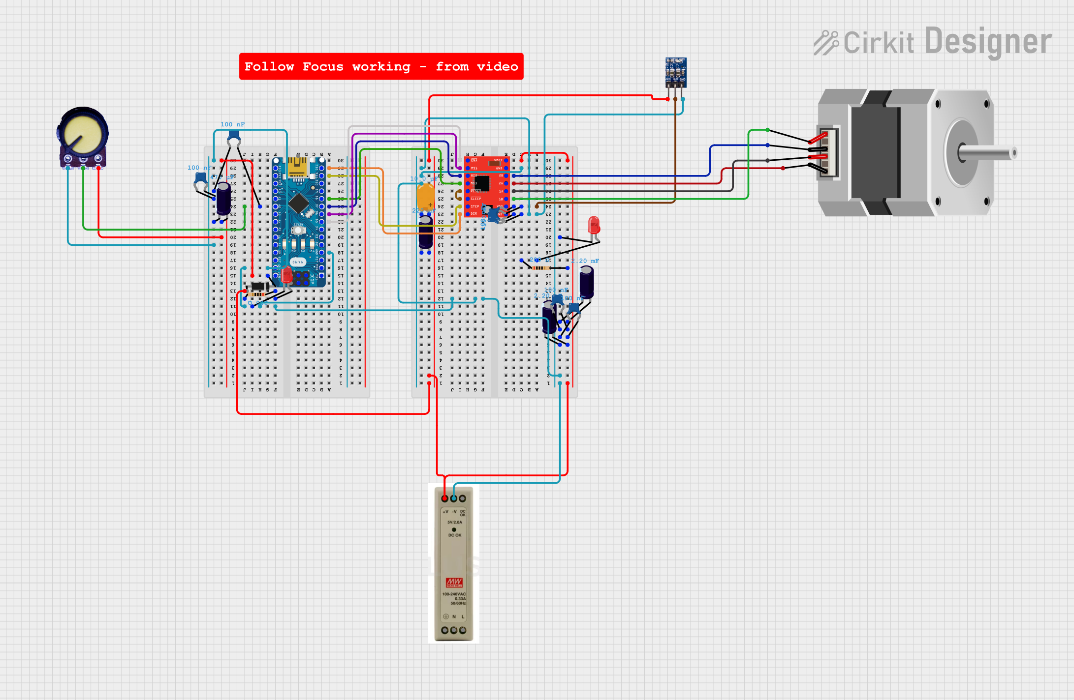
This circuit incorporates an Arduino Nano as the central microcontroller, interfaced with various components including LEDs, resistors, capacitors, a stepper motor driver, a stepper motor, a potentiometer, a diode, and a power supply unit (PSU). The Arduino Nano controls the stepper motor through the A4988 stepper motor driver and toggles LEDs on and off. The circuit is powered by a 5V PSU, and various capacitors are used for filtering and decoupling purposes. A potentiometer is included for adjustable control, likely for setting the reference voltage or current for the motor driver.
Component List
- Arduino Nano: A compact microcontroller board based on the ATmega328P, featuring digital and analog I/O pins.
- LED (Red): A two-pin light-emitting diode that emits red light.
- Resistor (200 Ohms): A passive two-terminal electrical component that provides resistance to the flow of current.
- A4988 Stepper Motor Driver: A complete microstepping motor driver with a built-in translator for easy operation.
- Ceramic Capacitor (100 nF): A small-value capacitor used for filtering and decoupling applications.
- Electrolytic Capacitor (2.2 µF, 220 nF, 47 µF): Capacitors with higher capacitance values, used for power supply filtering.
- Tantalum Capacitor (10 nF): A type of electrolytic capacitor that offers better performance and stability.
- ams1117 3.3: A low dropout voltage regulator that provides a 3.3V output.
- Potentiometer: A three-terminal resistor with an adjustable voltage divider.
- Diode: A two-terminal electronic component that conducts current primarily in one direction.
- Stepper Motor (Bipolar): A motor that divides a full rotation into a number of equal steps, ideal for precise control.
- 5V PSU: A power supply unit that provides a regulated 5V output.
- Comment: A non-electrical component used for annotations or notes within the circuit design.
Wiring Details
Arduino Nano
- GND: Connected to the cathodes of LEDs, ground pins of capacitors, A4988 GND, AMS1117 GND, potentiometer GND, and PSU GND.
- VIN: Connected to the cathode of the diode, and through capacitors to the potentiometer VCC.
- D5: Connected to the ENABLE pin of the A4988 stepper motor driver.
- D6: Connected to the MS1 pin of the A4988 stepper motor driver.
- D7: Connected to the MS2 pin of the A4988 stepper motor driver.
- A2: Connected to the potentiometer output and a ceramic capacitor.
- D8: Connected to the MS3 pin of the A4988 stepper motor driver.
- D11/MOSI: Connected to the STEP pin of the A4988 stepper motor driver.
- D12/MISO: Connected to the DIR pin of the A4988 stepper motor driver.
- D13/SCK: No specific connection detailed.
- RESET: No specific connection detailed.
LEDs (Red)
- Cathode: Connected to Arduino Nano GND.
- Anode: Connected to one side of the corresponding 200 Ohm resistors.
Resistors (200 Ohms)
- Pin1/Pin2: One pin connected to the anode of an LED, the other pin open or connected to a voltage source not specified.
A4988 Stepper Motor Driver
- ENABLE, MS1, MS2, MS3, STEP, DIR: Controlled by Arduino Nano.
- VMOT: Connected to the positive side of the PSU through a tantalum capacitor.
- GND: Connected to Arduino Nano GND.
- VDD: Connected to AMS1117 3.3V OUT through ceramic capacitors.
- 1A, 1B, 2A, 2B: Connected to the corresponding pins of the stepper motor.
- SLEEP, RESET: Connected together, no external control specified.
Capacitors
- Ceramic (100 nF): Connected across various power supply lines for decoupling.
- Electrolytic (2.2 µF, 220 nF, 47 µF): Connected across power supply lines for filtering.
- Tantalum (10 nF): Connected to the positive side of the PSU.
AMS1117 3.3
- VIN: Connected to the positive side of the PSU.
- OUT: Connected to the VDD of the A4988 stepper motor driver.
- GND: Connected to Arduino Nano GND.
Potentiometer
- GND: Connected to Arduino Nano GND.
- Output: Connected to Arduino Nano A2.
- VCC: Connected to Arduino Nano VIN through a diode and a ceramic capacitor.
Diode
- Cathode: Connected to Arduino Nano VIN.
- Anode: No specific connection detailed.
Stepper Motor (Bipolar)
- A, B, C, D: Connected to the corresponding outputs of the A4988 stepper motor driver.
5V PSU
- 5V+: Connected to the positive side of the tantalum capacitor and electrolytic capacitors.
- GND: Connected to Arduino Nano GND.
Documented Code
// Pin assignment
const int ledPin = 2; // LED connected to digital pin D2

void setup() {
  // Initialize the digital pin as an output.
  pinMode(ledPin, OUTPUT);
}

void loop() {
  // Turn the LED on (HIGH is the voltage level)
  digitalWrite(ledPin, HIGH);
  // Wait for a second
  delay(1000);
  // Turn the LED off by making the voltage LOW
  digitalWrite(ledPin, LOW);
  // Wait for a second
  delay(1000);
}
Filename: sketch.ino
This code is designed to blink an LED connected to digital pin D2 of the Arduino Nano. The LED is turned on for one second and then turned off for one second in a continuous loop.