
Arduino 101-Based Smart Soil Monitoring System with NPK, Moisture, and Temperature Sensors
View and Edit Project In Cirkit Designer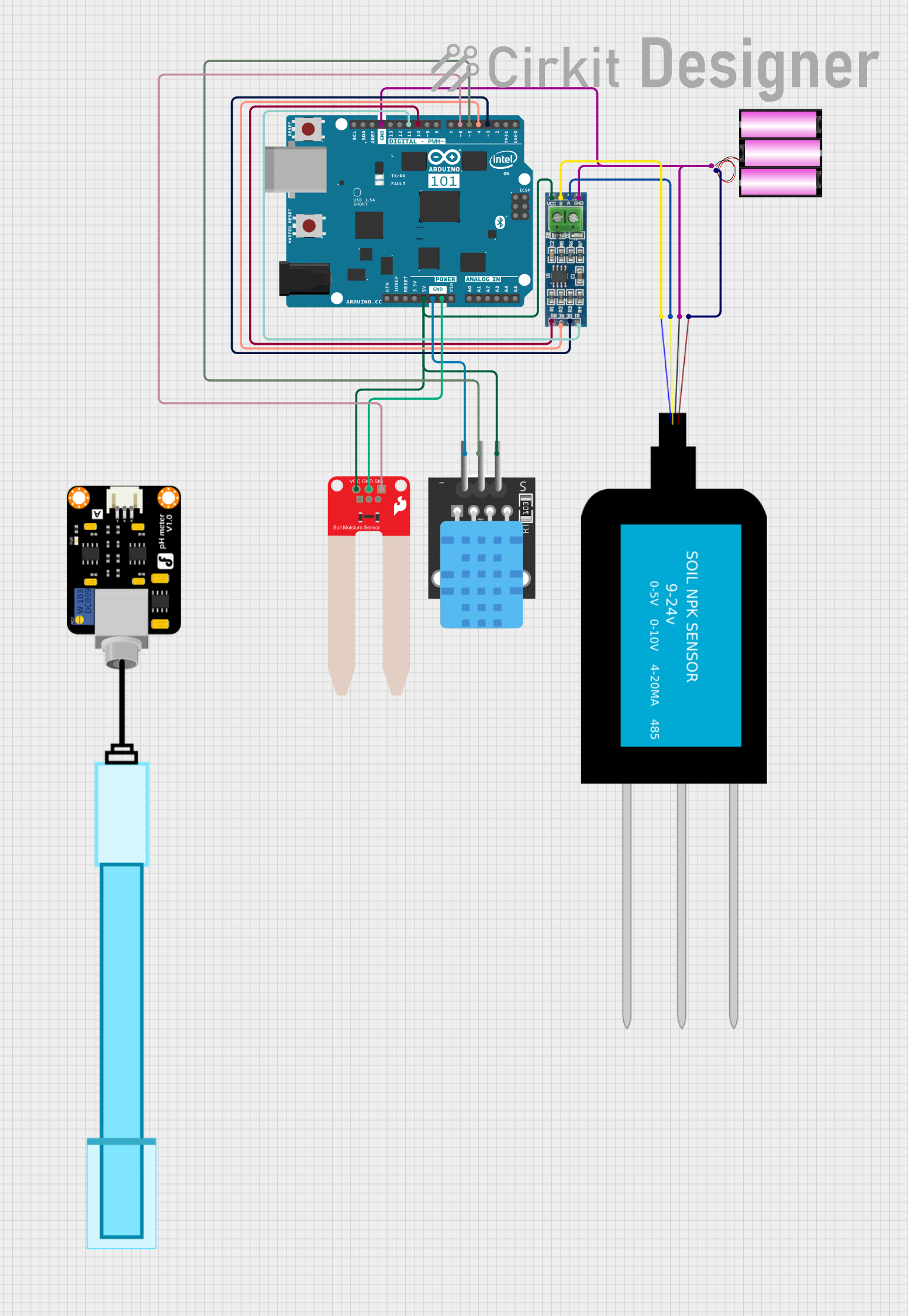
Circuit Documentation
Summary
This document provides a detailed overview of a circuit that includes various sensors, an Arduino 101 microcontroller, a 12V battery, and an RS-485 module. The circuit is designed to measure soil moisture, temperature, pH, and NPK levels using respective sensors. The Arduino 101 microcontroller processes the sensor data and communicates with other components via the RS-485 module.
Component List
NPK Soil Sensor
- Pins: VCC, GND, A, B
- Description: Measures the levels of Nitrogen (N), Phosphorus (P), and Potassium (K) in the soil.
- Purpose: To provide soil nutrient data.
TEMP Sensor
- Pins: 5V, D3, GND
- Description: Measures the temperature.
- Purpose: To provide temperature data.
SparkFun Soil Moisture Sensor
- Pins: VCC, GND, SIG
- Description: Measures the soil moisture level.
- Purpose: To provide soil moisture data.
Arduino 101
- Pins: A5/SCL, A4/SDA, AREF, GND, D13/SCK, D12/MISO, D11 PWM/MOSI, D10 PWM/SS, D9 PWM, D8, D7, D6 PWM, D5 PWM, D4, D3 PWM, D2, D1/TX, D0/RX, AIN, ioref, RESET, 3V3, 5V, VIN, A0, A1, A2, A3, ICSP MISO, ICSP SCK, ICSP MOSI
- Description: A microcontroller board based on the Intel Curie module.
- Purpose: To process sensor data and control other components.
Battery 12V
- Pins: +, -
- Description: Provides power to the circuit.
- Purpose: To supply power to the components.
RS-485 Module
- Pins: VCC, B, A, GND, RO, RE, DE, DI
- Description: A communication module for RS-485 protocol.
- Purpose: To enable communication between the Arduino and other devices.
PH Meter
- Pins: Signal, VCC, GND
- Description: Measures the pH level of the soil.
- Purpose: To provide soil pH data.
Wiring Details
NPK Soil Sensor
- VCC connected to + of Battery 12V
- GND connected to GND of RS-485 Module, - of Battery 12V, and GND of Arduino 101
- A connected to A of RS-485 Module
- B connected to B of RS-485 Module
TEMP Sensor
- 5V connected to 5V of Arduino 101
- D3 connected to D5 PWM of Arduino 101
- GND connected to GND of Arduino 101
SparkFun Soil Moisture Sensor
- VCC connected to 5V of Arduino 101
- GND connected to GND of Arduino 101
- SIG connected to D6 PWM of Arduino 101
Arduino 101
- 5V connected to VCC of RS-485 Module, VCC of SparkFun Soil Moisture Sensor, and 5V of TEMP Sensor
- GND connected to GND of RS-485 Module, GND of Battery 12V, GND of SparkFun Soil Moisture Sensor, and GND of TEMP Sensor
- D5 PWM connected to D3 of TEMP Sensor
- D6 PWM connected to SIG of SparkFun Soil Moisture Sensor
- D11 PWM/MOSI connected to DI of RS-485 Module
- D10 PWM/SS connected to RO of RS-485 Module
- D4 connected to RE of RS-485 Module
- D3 PWM connected to DE of RS-485 Module
Battery 12V
- + connected to VCC of NPK Soil Sensor
- - connected to GND of NPK Soil Sensor, GND of RS-485 Module, and GND of Arduino 101
RS-485 Module
- VCC connected to 5V of Arduino 101
- GND connected to GND of NPK Soil Sensor, - of Battery 12V, and GND of Arduino 101
- A connected to A of NPK Soil Sensor
- B connected to B of NPK Soil Sensor
- DI connected to D11 PWM/MOSI of Arduino 101
- RO connected to D10 PWM/SS of Arduino 101
- RE connected to D4 of Arduino 101
- DE connected to D3 PWM of Arduino 101
PH Meter
- Signal (not connected in the provided net list)
- VCC (not connected in the provided net list)
- GND (not connected in the provided net list)
Documented Code
Arduino 101 Code
void setup() {
  // put your setup code here, to run once:

}

void loop() {
  // put your main code here, to run repeatedly:

}
Battery 12V Code
void setup() {
  // put your setup code here, to run once:

}

void loop() {
  // put your main code here, to run repeatedly:

}
This documentation provides a comprehensive overview of the circuit, including the components used, their wiring details, and the code for the microcontrollers.