
Circuit Documentation
Summary of the Circuit
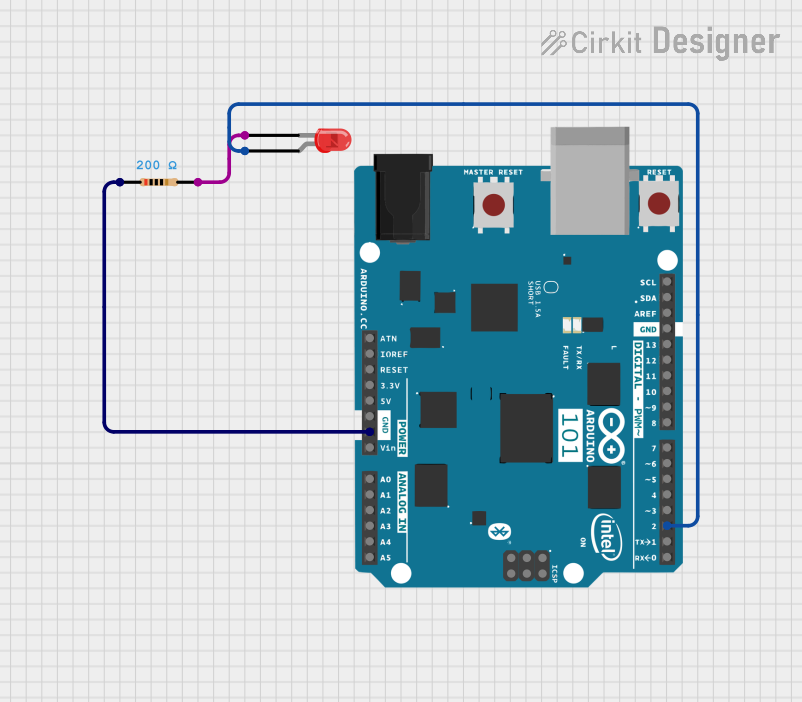
The circuit described by the provided inputs consists of an Arduino 101 microcontroller, a resistor, and a red two-pin LED. The Arduino 101 is programmed to blink the LED on and off at a one-second interval. The LED is connected to the Arduino through a resistor, which limits the current to protect the LED from damage.
Component List
Arduino 101
- Description: A microcontroller board based on the Intel Curie Module, designed for building IoT applications.
- Pins: A5/SCL, A4/SDA, AREF, GND, D13/SCK, D12/MISO, D11 PWM/MOSI, D10 PWM/SS, D9 PWM, D8, D7, D6 PWM, D5 PWM, D4, D3 PWM, D2, D1/TX, D0/RX, AIN, ioref, RESET, 3V3, 5V, VIN, A0, A1, A2, A3, ICSP MISO, ICSP SCK, ICSP MOSI.
- Purpose: Acts as the control unit for the circuit, driving the LED and managing the timing for blinking.
Resistor
- Description: A passive two-terminal electrical component that implements electrical resistance as a circuit element.
- Pins: pin1, pin2.
- Properties: 200 Ohms resistance.
- Purpose: Limits the current flowing through the LED to prevent it from burning out.
LED: Two Pin (red)
- Description: A red light-emitting diode that emits light when a current flows through it.
- Pins: cathode, anode.
- Purpose: Emits light when powered, indicating the output state of the Arduino's digital pin.
Wiring Details
Arduino 101
- GND is connected to the pin1 of the Resistor.
- D2 is connected to the anode of the LED: Two Pin (red).
Resistor
- pin1 is connected to the GND of the Arduino 101.
- pin2 is connected to the cathode of the LED: Two Pin (red).
LED: Two Pin (red)
- cathode is connected to the pin2 of the Resistor.
- anode is connected to the D2 of the Arduino 101.
Documented Code
Arduino 101 - sketch.ino
void setup() {
  pinMode(2, OUTPUT); // Set digital pin 2 as an output pin
}

void loop() {
  digitalWrite(2, HIGH); // Turn the LED on (HIGH is the voltage level)
  delay(1000);           // Wait for a second
  digitalWrite(2, LOW);  // Turn the LED off by making the voltage LOW
  delay(1000);           // Wait for a second
}
Description: This code configures pin 2 of the Arduino 101 as an output and then toggles it between HIGH and LOW states with a one-second delay between each state change. This results in the LED blinking on and off at one-second intervals.