
Arduino-Based Security System with Fingerprint Authentication and Voice Recognition
View and Edit Project In Cirkit Designer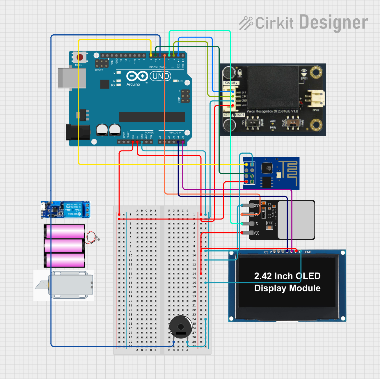
Circuit Documentation
Summary
This circuit integrates various components to create a system capable of wireless communication, user interaction through a display and voice recognition, biometric scanning, and audio feedback. The core of the circuit is an Arduino UNO microcontroller, which interfaces with an ESP8266 ESP-01 WiFi module for network connectivity, an OLED display for visual output, a DF Robot Gravity Voice Recognition Module for voice input, and a Fingerprint Scanner for biometric input. A Piezo Buzzer provides audio feedback. The circuit is powered by the Arduino UNO's voltage regulators, with ground connections distributed across the components.
Component List
Piezo Buzzer
- Description: A simple audio signaling device that can be used to generate tones of varying frequencies.
- Purpose: To provide audio feedback to the user.
OLED Display 2.42"
- Description: A small graphical display with I2C communication, capable of displaying text and graphics.
- Purpose: To visually display information to the user.
Fingerprint Scanner
- Description: A biometric sensor that captures fingerprints for identification purposes.
- Purpose: To authenticate users through their fingerprints.
DF Robot Gravity Voice Recognition Module
- Description: A module that can recognize voice commands and convert them into digital signals.
- Purpose: To allow voice control of the system.
ESP8266 ESP-01 WiFi Module
- Description: A compact WiFi module that enables the microcontroller to connect to wireless networks.
- Purpose: To provide network connectivity for remote communication and control.
Arduino UNO
- Description: A microcontroller board based on the ATmega328P, with digital and analog I/O pins.
- Purpose: To serve as the central processing unit of the circuit, controlling the interactions between components.
Relay Module 5V-30V
- Description: An electrically operated switch that allows controlling high power devices with low power signals.
- Purpose: To control power-heavy devices like solenoids or motors.
12V Solenoid Lock
- Description: An electromagnetic lock that can be actuated using electrical power.
- Purpose: To provide a locking mechanism controlled by the circuit.
Battery 12V
- Description: A 12V power source.
- Purpose: To supply power to components requiring higher voltages than what the Arduino can provide.
Wiring Details
Piezo Buzzer
- Pin 1: Connected to Arduino UNO's Digital Pin 5 (D5)
- Pin 2: Connected to Ground (GND)
OLED Display 2.42"
- GND: Connected to Ground (GND)
- VCC: Connected to Arduino UNO's 5V output
- SCK: Connected to Arduino UNO's Analog Pin 5 (A5)
- SDA: Connected to Arduino UNO's Analog Pin 4 (A4)
- RES: Not connected in the provided net list
- DC: Not connected in the provided net list
- CS: Not connected in the provided net list
Fingerprint Scanner
- VCC: Connected to Arduino UNO's 5V output
- TX: Connected to Arduino UNO's Digital Pin 3 (D3)
- RX: Connected to Arduino UNO's Digital Pin 4 (D4)
- GND: Connected to Ground (GND)
DF Robot Gravity Voice Recognition Module
- D/T: Connected to Arduino UNO's Digital Pin 1 (D1)
- C/R: Connected to Arduino UNO's Digital Pin 2 (D2)
- GND: Connected to Ground (GND)
- VCC: Connected to Arduino UNO's 5V output
- -: Not connected in the provided net list
- +: Not connected in the provided net list
ESP8266 ESP-01 WiFi Module
- TXD: Connected to Arduino UNO's Digital Pin 7 (D7)
- CH_PD: Not connected in the provided net list
- RST: Not connected in the provided net list
- VCC: Connected to Arduino UNO's 3.3V output
- GND: Connected to Ground (GND)
- GPIO_2: Not connected in the provided net list
- GPIO_0: Not connected in the provided net list
- RXD: Connected to Arduino UNO's Digital Pin 6 (D6)
Relay Module 5V-30V
- Common Contact: Not connected in the provided net list
- Normally Open: Not connected in the provided net list
- Normally Closed: Not connected in the provided net list
- Trigger: Not connected in the provided net list
- V-: Not connected in the provided net list
- V+: Not connected in the provided net list
12V Solenoid Lock
- -: Not connected in the provided net list
- +: Not connected in the provided net list
Battery 12V
- +: Not connected in the provided net list
- -: Not connected in the provided net list
Documented Code
Arduino UNO Code (sketch.ino)
void setup() {
  // put your setup code here, to run once:

}

void loop() {
  // put your main code here, to run repeatedly:

}
Note: The provided code is a template and does not include any functionality. It needs to be populated with the logic to control the components based on the requirements of the circuit's application.