
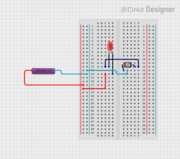
Circuit Documentation
Summary
This circuit consists of a Light Dependent Resistor (LDR), a red LED, and a 3.7V battery. The circuit is designed to light up the LED when the LDR detects a certain level of light. The LDR and LED are connected in such a way that the LED will turn on when the resistance of the LDR changes due to varying light conditions.
Component List
Photocell (LDR)
- Pins: pin 0, pin 1
- Description: A light-dependent resistor that changes its resistance based on the amount of light it is exposed to.
- Purpose in Circuit: To detect light levels and control the LED.
LED: Two Pin (red)
- Pins: cathode, anode
- Description: A red light-emitting diode.
- Purpose in Circuit: To emit light when powered.
3.7V Battery
- Pins: +, -
- Description: A power source providing 3.7 volts.
- Purpose in Circuit: To supply power to the circuit.
Wiring Details
Photocell (LDR)
- pin 0 is connected to the - pin of the 3.7V battery.
- pin 1 is connected to the cathode pin of the LED: Two Pin (red).
LED: Two Pin (red)
- cathode is connected to the pin 1 of the Photocell (LDR).
- anode is connected to the + pin of the 3.7V battery.
3.7V Battery
- + is connected to the anode pin of the LED: Two Pin (red).
- - is connected to the pin 0 of the Photocell (LDR).
Code
There is no microcontroller code associated with this circuit.
This documentation provides a comprehensive overview of the circuit, including a summary, detailed component descriptions, and wiring details. The circuit is simple and does not include any microcontroller code.