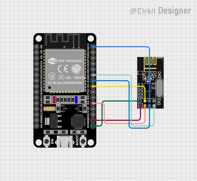
ESP32 and NRF24L01 Wireless Communication Module

Circuit Documentation
Summary
This circuit integrates an ESP32 microcontroller with an NRF24L01 wireless transceiver module. The ESP32 is a versatile microcontroller with Wi-Fi and Bluetooth capabilities, while the NRF24L01 module provides a cost-effective wireless communication solution. The circuit is designed to enable wireless data transmission between the ESP32 and other devices equipped with NRF24L01 modules.
Component List
ESP32 (30 pin)
- Description: A powerful microcontroller with Wi-Fi and Bluetooth capabilities, featuring a wide range of GPIO pins for interfacing with various peripherals.
- Purpose: Acts as the central processing unit of the circuit, controlling the NRF24L01 module and handling data communication tasks.
NRF24L01
- Description: A 2.4GHz wireless transceiver module that allows for easy and inexpensive wireless communication.
- Purpose: Provides wireless communication capabilities to the circuit, interfacing with the ESP32 for data transmission.
Wiring Details
ESP32 (30 pin)
- EN: Not connected in this circuit.
- VP: Not connected in this circuit.
- VN: Not connected in this circuit.
- D34: Not connected in this circuit.
- D35: Not connected in this circuit.
- D32: Not connected in this circuit.
- D33: Not connected in this circuit.
- D25: Not connected in this circuit.
- D26: Not connected in this circuit.
- D27: Not connected in this circuit.
- D14: Not connected in this circuit.
- D12: Not connected in this circuit.
- D13: Not connected in this circuit.
- GND: Connected to NRF24L01 GND.
- Vin: Not connected in this circuit.
- D23: Connected to NRF24L01 MOSI.
- D22: Not connected in this circuit.
- TX0: Not connected in this circuit.
- RX0: Not connected in this circuit.
- D21: Not connected in this circuit.
- D19: Connected to NRF24L01 MISO.
- D18: Connected to NRF24L01 SCK.
- D5: Connected to NRF24L01 CSN.
- TX2: Not connected in this circuit.
- RX2: Not connected in this circuit.
- D4: Connected to NRF24L01 CE.
- D2: Not connected in this circuit.
- D15: Not connected in this circuit.
- 3V3: Connected to NRF24L01 VCC (3V).
NRF24L01
- IRQ (not used): Not connected in this circuit.
- MOSI: Connected to ESP32 D23.
- CSN: Connected to ESP32 D5.
- VCC (3V): Connected to ESP32 3V3.
- GND: Connected to ESP32 GND.
- CE: Connected to ESP32 D4.
- SCK: Connected to ESP32 D18.
- MISO: Connected to ESP32 D19.
Code Documentation
No code has been provided for the microcontrollers in the circuit. To fully utilize the capabilities of the ESP32 and NRF24L01, embedded code is required to handle initialization, data transmission, and reception tasks. The code would typically be written in C or C++ and uploaded to the ESP32 using the appropriate development environment, such as the Arduino IDE or ESP-IDF.