
Arduino Nano Controlled NRF24L01 Wireless Communication System
View and Edit Project In Cirkit Designer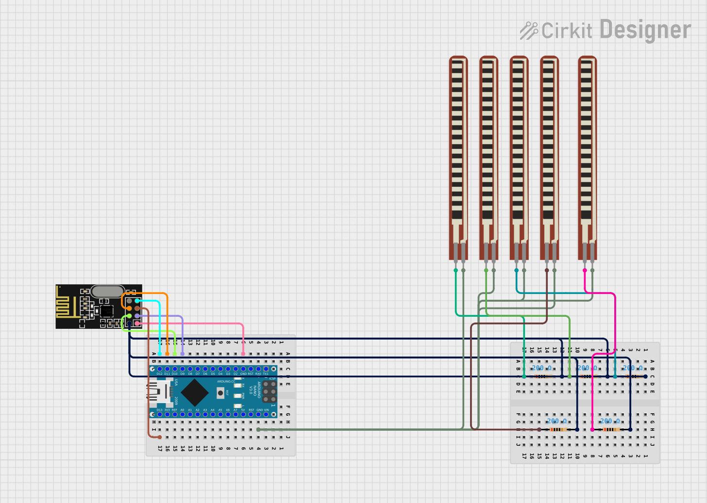
Circuit Documentation
Summary
This circuit integrates an Arduino Nano microcontroller with an NRF24L01 wireless transceiver module. The circuit also includes a network of resistors and flex resistors that may be used for various purposes such as voltage division, current limiting, or sensing applications. The Arduino Nano is configured to communicate with the NRF24L01 module using SPI (Serial Peripheral Interface) and additional control lines.
Component List
Arduino Nano
- Microcontroller board based on the ATmega328P
- Pins: D1/TX, D0/RX, RESET, GND, D2 to D13, VIN, 5V, A0 to A7, AREF, 3V3
- Used as the main processing unit of the circuit.
NRF24L01
- 2.4GHz wireless transceiver module
- Pins: IRQ (not used), MOSI, CSN, VCC (3V), GND, CE, SCK, MISO
- Enables wireless communication capabilities for the circuit.
Resistor (200 Ohms)
- Passive electrical component providing resistance
- Pins: pin1, pin2
- Used for current limiting or voltage division.
2.2 inch Basic Flex Resistor
- Flexible resistor that changes resistance with bending
- Pins: Pin 2, pin 1
- Typically used for sensing applications.
Wiring Details
Arduino Nano
- GND connected to the ground network including flex resistors and NRF24L01 GND.
- D9 connected to NRF24L01 CE.
- D10 connected to NRF24L01 CSN.
- D11/MOSI connected to NRF24L01 MOSI.
- D12/MISO connected to NRF24L01 MISO.
- D13/SCK connected to NRF24L01 SCK.
NRF24L01
- VCC (3V) connected to a network of 200 Ohm resistors.
- GND connected to the Arduino Nano GND.
- CE connected to Arduino Nano D9.
- CSN connected to Arduino Nano D10.
- MOSI connected to Arduino Nano D11/MOSI.
- MISO connected to Arduino Nano D12/MISO.
- SCK connected to Arduino Nano D13/SCK.
Resistor (200 Ohms)
- One pin connected to NRF24L01 VCC (3V).
- Other pin connected to various flex resistors.
2.2 inch Basic Flex Resistor
- One pin connected to a 200 Ohm resistor.
- Other pin connected to the ground network.
Documented Code
Arduino Nano - sketch.ino
void setup() {
  // put your setup code here, to run once:

}

void loop() {
  // put your main code here, to run repeatedly:

}
Arduino Nano - documentation.txt
(No additional documentation provided)
This concludes the documentation for the provided circuit. The circuit is designed for basic interfacing between the Arduino Nano and the NRF24L01 module, with additional components for various potential applications. The code provided is a template and will need to be populated with the logic required for the intended application.