
ESP32 Wi-Fi Controlled Smart Light System with Voice Assistant
View and Edit Project In Cirkit Designer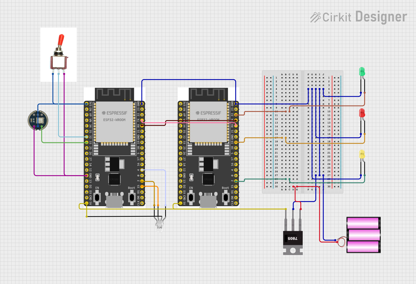
Circuit Documentation
Summary
This circuit involves multiple components including LEDs, a toggle switch, a microphone, a voltage regulator, a battery, and ESP32 microcontrollers. The circuit is designed to control LEDs based on commands received via serial communication and to convert text to speech using Google Cloud's Text-to-Speech API.
Component List
INMP441
- Description: MEMS microphone
- Pins: GND, VDD, SD, L/R, WS, SCK
Toggle Switch
- Description: A simple toggle switch
- Pins: Vcc, Sig, Gnd
LED: Two Pin (green)
- Description: Green LED
- Pins: cathode, anode
LED: Two Pin (yellow)
- Description: Yellow LED
- Pins: cathode, anode
LED: Two Pin (red)
- Description: Red LED
- Pins: cathode, anode
Battery 12V
- Description: 12V battery
- Pins: +, -
7805
- Description: Voltage regulator
- Pins: Vin, Gnd, Vout
LED: Four Pin
- Description: RGB LED
- Pins: red cathode, common anode, green cathode, blue cathode
ESP32 Wroom Dev Kit
- Description: ESP32 microcontroller development board
- Pins: 3V3, EN, VP, VN, GPIO 34, GPIO 35, GPIO 32, GPIO 33, GPIO 25, GPIO 26, GPIO 27, GPIO 14, GND, GPIO 13, SD2, SD3, CMD, V5, GPIO 23, GPIO 22, TXD, RXD, GPIO 21, GPIO 19, GPIO 18, GPIO 5, GPIO 17, GPIO 16, GPIO 4, GPIO 0, GPIO 2, GPIO 15, SD1, SD0, CLK
Wiring Details
INMP441
- VDD connected to Vcc of Toggle Switch and 3V3 of ESP32 Wroom Dev Kit
- SD connected to GPIO 33 of ESP32 Wroom Dev Kit
- GND connected to Gnd of Toggle Switch and GND of ESP32 Wroom Dev Kit
Toggle Switch
- Vcc connected to VDD of INMP441 and 3V3 of ESP32 Wroom Dev Kit
- Sig connected to GPIO 32 of ESP32 Wroom Dev Kit
- Gnd connected to GND of ESP32 Wroom Dev Kit and GND of INMP441
LED: Two Pin (green)
- cathode connected to GND of ESP32 Wroom Dev Kit
- anode connected to GPIO 22 of ESP32 Wroom Dev Kit
LED: Two Pin (yellow)
- cathode connected to - of Battery 12V
- anode connected to GPIO 2 of ESP32 Wroom Dev Kit
LED: Two Pin (red)
- cathode connected to - of Battery 12V
- anode connected to GPIO 19 of ESP32 Wroom Dev Kit
Battery 12V
- + connected to Vin of 7805
- - connected to cathode of LED: Two Pin (yellow), LED: Two Pin (red), LED: Two Pin (green), and GND of ESP32 Wroom Dev Kit
7805
- Vin connected to + of Battery 12V
- Gnd connected to - of Battery 12V
- Vout connected to V5 of ESP32 Wroom Dev Kit and common anode of LED: Four Pin
LED: Four Pin
- red cathode connected to GPIO 4 of ESP32 Wroom Dev Kit
- common anode connected to V5 of ESP32 Wroom Dev Kit
- green cathode connected to GPIO 15 of ESP32 Wroom Dev Kit
- blue cathode connected to GPIO 2 of ESP32 Wroom Dev Kit
ESP32 Wroom Dev Kit
- GND connected to - of Battery 12V
- 3V3 connected to Vcc of Toggle Switch and VDD of INMP441
- GPIO 22 connected to anode of LED: Two Pin (green)
- GPIO 19 connected to anode of LED: Two Pin (red)
- GPIO 2 connected to anode of LED: Two Pin (yellow)
- GPIO 32 connected to Sig of Toggle Switch
- GPIO 33 connected to SD of INMP441
- V5 connected to Vout of 7805 and common anode of LED: Four Pin
- TXD connected to RXD of another ESP32 Wroom Dev Kit
- RXD connected to TXD of another ESP32 Wroom Dev Kit
- GPIO 4 connected to red cathode of LED: Four Pin
- GPIO 15 connected to green cathode of LED: Four Pin
- GPIO 2 connected to blue cathode of LED: Four Pin
Code Documentation
ESP32 Wroom Dev Kit (Instance 1)
#include <WiFi.h>
#include <HTTPClient.h>
#include <ArduinoJson.h>
#include <Wire.h>
#include <I2S.h>  // For audio output over I2S (adjust if using PWM or other methods)

// WiFi credentials
const char* ssid = "Your_SSID";
const char* password = "Your_PASSWORD";

// Google Cloud API endpoint and API key
const String apiEndpoint = "https://texttospeech.googleapis.com/v1/text:synthesize";
const String apiKey = "YOUR_GOOGLE_CLOUD_API_KEY";

// Pin definitions for audio output
#define I2S_DOUT_PIN  25  // I2S Data out pin for audio
#define I2S_BCLK_PIN  26  // I2S Bit clock pin
#define I2S_LRC_PIN   27  // I2S Left/Right clock pin

// Setup WiFi
void setup() {
  // Start serial communication for debugging
  Serial.begin(115200);
  Serial.println("Connecting to WiFi...");

  // Connect to WiFi
  WiFi.begin(ssid, password);
  while (WiFi.status() != WL_CONNECTED) {
    delay(1000);
    Serial.print(".");
  }
  Serial.println("\nWiFi connected");

  // Initialize I2S for audio output
  I2S.begin(I2S_PHILIPS_MODE, 16000, 16);  // 16KHz, 16-bit depth for audio output

  // Example: Send a simple text to be converted to speech
  String textToConvert = "Hello, I am your assistant. How can I help you today?";
  convertTextToSpeech(textToConvert);
}

void loop() {
  // Add code to handle interactions here (e.g., listening for commands)
  // The voice output can be triggered based on your application logic
}

// Function to send text to Google Cloud Text-to-Speech API and get audio
void convertTextToSpeech(String text) {
  if (WiFi.status() != WL_CONNECTED) {
    Serial.println("WiFi not connected");
    return;
  }

  // Prepare HTTP request
  HTTPClient http;
  http.begin(apiEndpoint);
  http.addHeader("Content-Type", "application/json");
  http.addHeader("Authorization", "Bearer " + apiKey);  // Use API Key for authorization

  // Prepare the request payload (JSON)
  String payload = "{"
                   "\"input\": {\"text\": \"" + text + "\"},"
                   "\"voice\": {\"languageCode\": \"en-US\", \"ssmlGender\": \"NEUTRAL\"},"
                   "\"audioConfig\": {\"audioEncoding\": \"MP3\"}"
                   "}";

  // Send POST request
  int httpResponseCode = http.POST(payload);
  String response = http.getString();
  http.end();

  // Check for successful response
  if (httpResponseCode == 200) {
    Serial.println("Response from API received successfully.");
    playAudio(response);  // Play the audio
  } else {
    Serial.println("Error in API response: " + String(httpResponseCode));
  }
}

// Function to parse the