Cirkit Designer
Your all-in-one circuit design IDE
Home /
Project Documentation
Wi-Fi Enabled Automated Water Level Control System with Arduino and ESP-8266

Circuit Documentation
Summary
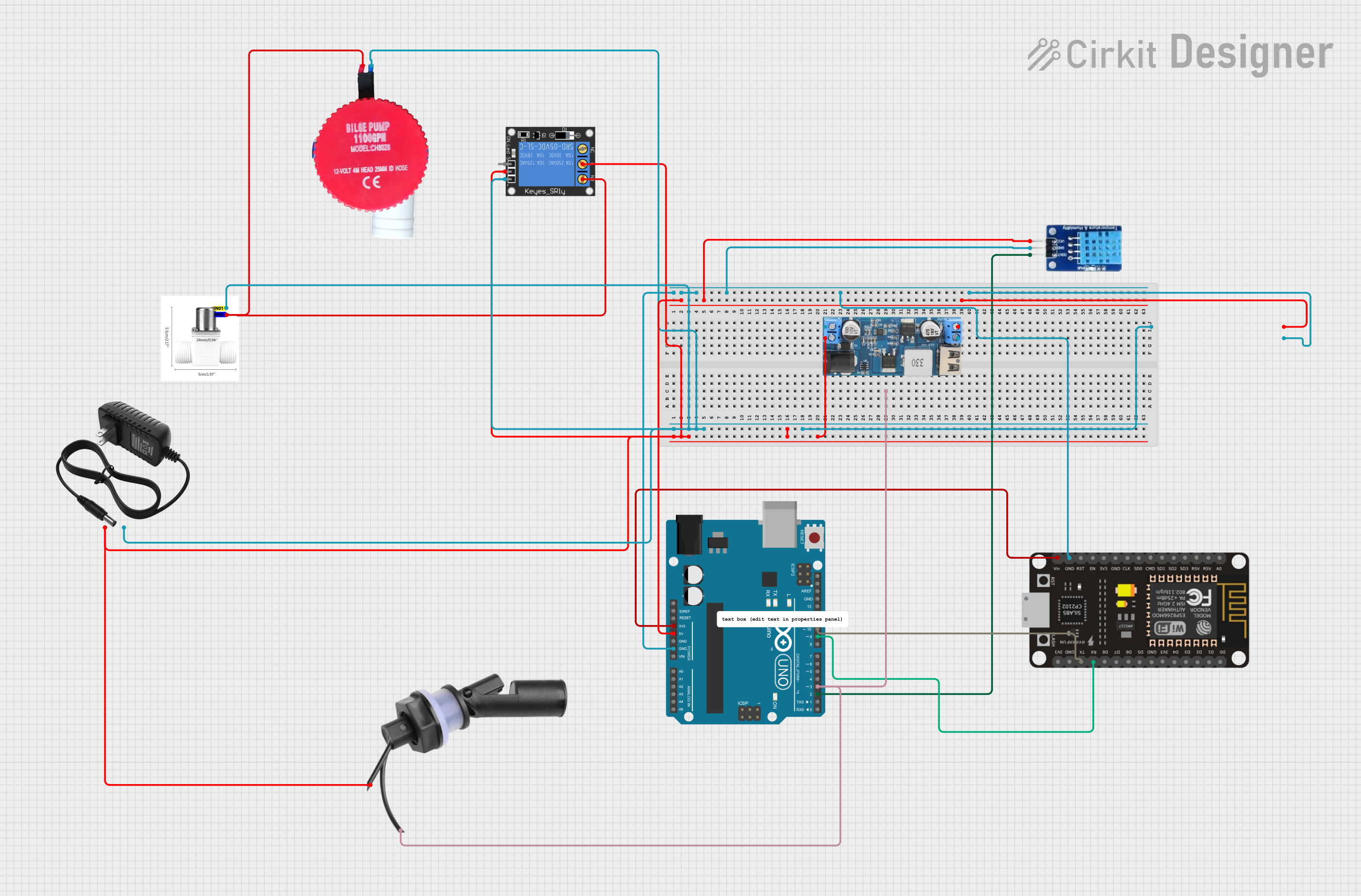
This document provides a detailed overview of a circuit designed to interface various components including sensors, actuators, power supplies, and microcontrollers. The circuit is capable of monitoring environmental conditions, controlling power to devices, and communicating with external systems. The core of the circuit is built around an Arduino UNO and an ESP-8266 Controller, which are responsible for processing data and controlling the connected devices.
Component List
DHT11
- Description: Temperature and humidity sensor.
- Pins: DATA, GND, VCC
Valve Solenoid Water
- Description: Electrically-controlled valve for water flow.
- Pins: IN01, IN02
1-Channel Relay (5V 10A)
- Description: Relay module for controlling high power devices.
- Pins: NC, signal, C, power, NO, ground
Bilge Pump 12V
- Description: Electric pump for removing bilge water.
- Pins: P, G
Water Level Float Switch Sensor
- Description: Sensor for detecting water level.
- Pins: Wire1, Wire2
12v Power Supply
- Description: Power supply unit providing 12V output.
- Pins: +, -
Arduino UNO
- Description: Microcontroller board based on the ATmega328P.
- Pins: UNUSED, IOREF, Reset, 3.3V, 5V, GND, Vin, A0-A5, SCL, SDA, AREF, D0-D13
ESP-8266 Controller
- Description: Wi-Fi capable microcontroller module.
- Pins: A0, RSV, SD3, SD5, SD1, CMD, D0-D8, 3V3, GND, SD0, CLK, RST, EN, RX, TX, Vin, 5V
12v to 5v Step Down Power Converter
- Description: Converter to step down voltage from 12V to 5V.
- Pins: VIN 9v-36v, VIN+, VIN-, USB OUTPUT 5V, 5v OUTPUT, GND
Wiring Details
DHT11
- DATA connected to Arduino UNO D2
- GND connected to common ground
- VCC connected to Arduino UNO 5V
Valve Solenoid Water
- IN01 connected to 12v power supply -
- IN02 connected to 1-Channel Relay NO and Bilge Pump 12V P
1-Channel Relay (5V 10A)
- NC not connected
- signal not detailed in the net list
- C connected to 12v power supply +
- power connected to 12v power supply +
- NO connected to Valve Solenoid Water IN02 and Bilge Pump 12V P
- ground connected to common ground
Bilge Pump 12V
- P connected to Valve Solenoid Water IN02 and 1-Channel Relay NO
- G connected to 12v power supply -
Water Level Float Switch Sensor
- Wire1 connected to 12v to 5v Step Down Power Converter VIN+ and 12v power supply +
- Wire2 connected to Arduino UNO D3
12v Power Supply
- connected to Water Level Float Switch Sensor Wire1, 12v to 5v Step Down Power Converter VIN+, and 1-Channel Relay C and power
- connected to Valve Solenoid Water IN01 and Bilge Pump 12V G
Arduino UNO
- D2 connected to DHT11 DATA
- D3 connected to Water Level Float Switch Sensor Wire2
- D9 connected to ESP-8266 Controller RX
- D10 connected to ESP-8266 Controller TX
- 3.3V connected to ESP-8266 Controller Vin
- 5V connected to DHT11 VCC and 12v to 5v Step Down Power Converter 5v OUTPUT
- GND connected to common ground
ESP-8266 Controller
- Vin connected to Arduino UNO 3.3V
- TX connected to Arduino UNO D10
- RX connected to Arduino UNO D9
- GND connected to common ground
12v to 5v Step Down Power Converter
- VIN 9v-36v not detailed in the net list
- VIN+ connected to Water Level Float Switch Sensor Wire1 and 12v power supply +
- VIN- connected to common ground
- USB OUTPUT 5V not detailed in the net list
- 5v OUTPUT connected to Arduino UNO 5V
- GND connected to common ground
Documented Code
Arduino UNO Code (sketch.ino)
void setup() {
  // put your setup code here, to run once:

}

void loop() {
  // put your main code here, to run repeatedly:

}
ESP-8266 Controller Code
No code provided for the ESP-8266 Controller in the input data.
Note: The provided code for the Arduino UNO is a template and does not contain any functional code specific to the circuit. Additional code is required to control and interact with the connected components.