
Arduino Nano 33 BLE Magnetic Levitation System with Hall Sensor Feedback and Status LED Indicator
View and Edit Project In Cirkit Designer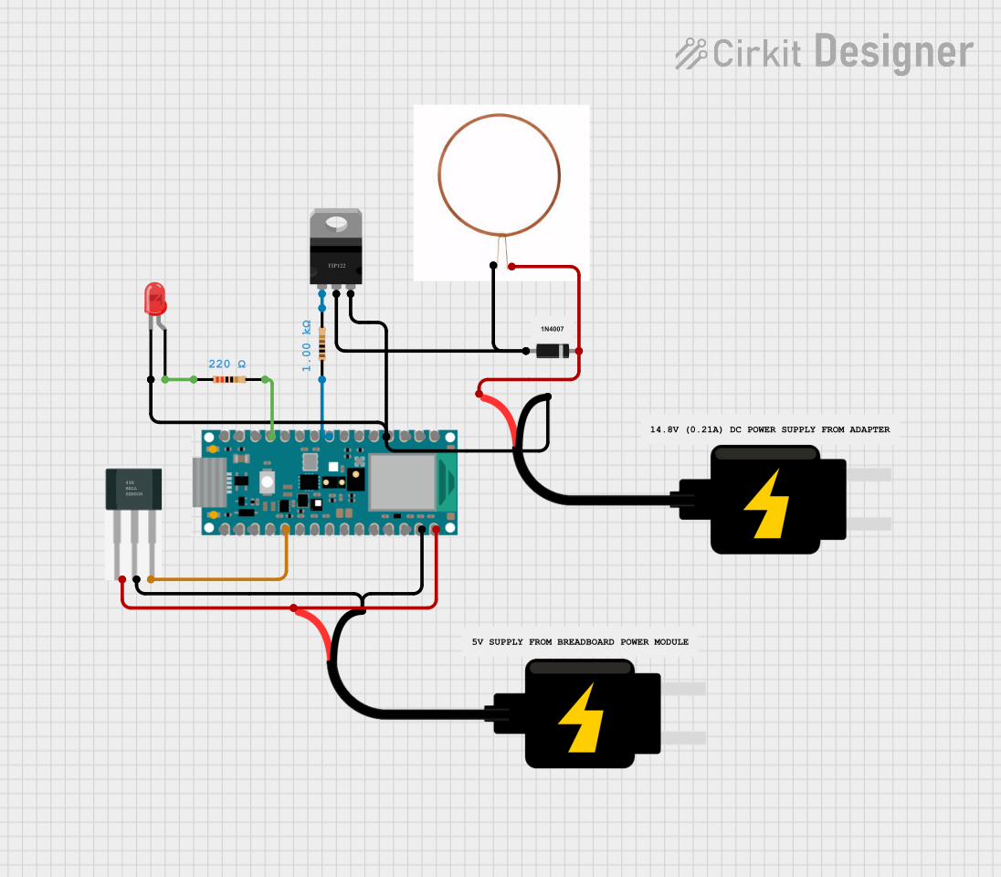
Circuit Documentation
Summary of the Circuit
This circuit is designed to control a magnetic levitation system using a Hall sensor, a TIP120 transistor, and an Arduino Nano 33 BLE. The Hall sensor detects the magnetic field strength, and the Arduino adjusts the current through a coil to levitate a magnetic object. Additionally, an LED is used to indicate the system status, lighting up when the coil is active.
Component List
Nano 33 BLE with pinout
- Microcontroller board based on the nRF52840.
- It has a variety of digital and analog pins for interfacing with various components.
DC Source 5V
- Provides a 5V power supply to the circuit.
- Two instances of this component are used to power different parts of the circuit.
Hall Sensor
- Senses the magnetic field strength.
- Outputs a voltage corresponding to the magnetic field strength it detects.
Diode
- Allows current to flow in one direction, protecting components from potential reverse current.
TIP120 Hi-Current Darlington Transistor
- Acts as a switch to control high current loads with a low current signal.
- In this circuit, it controls the current through the coil.
Resistor (1k Ohms)
- Limits the current flowing into the base of the TIP120 transistor.
Resistor (220 Ohms)
- Limits the current flowing through the LED to prevent damage.
Copper Coil
- Generates a magnetic field when current flows through it.
- Used in conjunction with the Hall sensor to levitate a magnetic object.
LED: Two Pin (red)
- Indicates the system status by lighting up when the coil is active.
Comments
- Four instances of comments are included, which may contain notes or explanations about the circuit design. These are not physical components.
Wiring Details
Nano 33 BLE with pinout
GNDconnected to the emitter of the TIP120 transistor, GND of the 5V DC source, and cathode of the LED.D5connected to one end of the 1k Ohm resistor.D9connected to one end of the 220 Ohm resistor.VINconnected to the VCC of the 5V DC source.A1connected to the signal pin of the Hall sensor.
DC Source 5V
VCCconnected to VIN of the Nano 33 BLE and the cathode of the diode.GNDconnected to GND of the Nano 33 BLE and the positive pin of the Hall sensor.
Hall Sensor
-connected to VIN of the Nano 33 BLE.+connected to GND of the Nano 33 BLE.Sconnected to A1 of the Nano 33 BLE.
Diode
cathodeconnected to VCC of the 5V DC source.anodeconnected to the collector of the TIP120 transistor.
TIP120 Hi-Current Darlington Transistor
BASEconnected to the other end of the 1k Ohm resistor.COLLECTORconnected to the anode of the diode and the negative end of the copper coil.EMITTERconnected to GND of the Nano 33 BLE.
Resistor (1k Ohms)
pin1connected to D5 of the Nano 33 BLE.pin2connected to the base of the TIP120 transistor.
Resistor (220 Ohms)
pin1connected to D9 of the Nano 33 BLE.pin2connected to the anode of the LED.
Copper Coil
+veconnected to the cathode of the diode.-veconnected to the collector of the TIP120 transistor.
LED: Two Pin (red)
cathodeconnected to GND of the Nano 33 BLE.anodeconnected to the other end of the 220 Ohm resistor.
Documented Code
/*
 * Arduino Sketch for Magnetic Levitation
 *
 * This code controls a magnetic levitation system using a Hall sensor and a
 * TIP120 transistor. The Hall sensor reads the magnetic field strength, and
 * the Arduino adjusts the current through a coil to levitate a magnetic object.
 * An LED is used to indicate the system status.
 */

const int hallSensorPin = A1; // Hall sensor output connected to A1
const int coilControlPin = 5;  // TIP120 base connected to D5
const int ledPin = 9;          // LED anode connected to D9

void setup() {
  pinMode(coilControlPin, OUTPUT); // Set coil control pin as output
  pinMode(ledPin, OUTPUT);         // Set LED pin as output
  pinMode(hallSensorPin, INPUT);   // Set Hall sensor pin as input
}

void loop() {
  int hallValue = analogRead(hallSensorPin); // Read Hall sensor value
  int coilValue = map(hallValue, 0, 1023, 0, 255); // Map sensor value to PWM
  analogWrite(coilControlPin, coilValue); // Control coil current
  if (coilValue > 128) {
    digitalWrite(ledPin, HIGH); // Turn on LED if coil is active
  } else {
    digitalWrite(ledPin, LOW);  // Turn off LED if coil is inactive
  }
  delay(10); // Small delay for stability
}
The code is written for the Arduino Nano 33 BLE and is responsible for reading the Hall sensor data, controlling the current through the coil, and managing the LED indicator.