
NodeMCU ESP8266-Based Smart Lift System with IR Sensors and Voice Commands
View and Edit Project In Cirkit Designer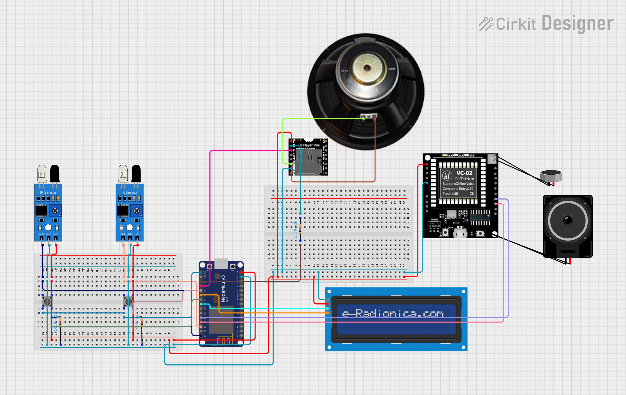
Circuit Documentation
Summary
This circuit is an IoT-based smart lift system designed for blind and disabled individuals. It integrates various components such as IR sensors, pushbuttons, an LCD screen, a DFPlayer module, and a VC-02 module to provide floor information and voice input capabilities. The IR sensors detect finger presence, and the system announces the corresponding floor through the speaker and displays it on the LCD. Voice commands can also be given to select a floor.
Component List
VC-02 Module
- Pins: NC, TCK OR IOB0, TMS OR IOB1, GND, Vcc, DAC_L, DAS_R, 3.3V O, SDA_5V, SCL_5V, SDA OR IOB3, SCL OR IOB2, IOA27, IOB8, RX(IOB6), TX(IOB7)
- Description: Voice command module
IR Sensor
- Pins: out, gnd, vcc
- Description: Infrared sensor for detecting finger presence
DFPlayer MINI
- Pins: VCC, BUSY, RX, USB -, TX, USB +, DAC_R, K2/ADC_KEY, DAC_L, K1/ADC_KEY, SPK1, IO 2, GND, SPK2, IO 1
- Description: MP3 player module
NodeMCU V3 ESP8266
- Pins: A0, GND, VU, S3, S2, S1, SC, S0, SK, 3V3, EN, RST, Vin, D0, D1, D2, D3, D4, D5, D6, D7, D8, RX, TX
- Description: Microcontroller for IoT applications
Resistor (1k Ohms)
- Pins: pin1, pin2
- Description: Resistor with 1k Ohms resistance
Resistor (10k Ohms)
- Pins: pin1, pin2
- Description: Resistor with 10k Ohms resistance
Speaker
- Pins: +, -
- Description: Speaker for audio output
Condenser Microphone
- Pins: pin1, pin2
- Description: Microphone for audio input
Loudspeaker
- Pins: pin1, pin2
- Description: Loudspeaker for audio output
LCD Screen 16x2 I2C
- Pins: SCL, SDA, VCC, GND
- Description: LCD screen for displaying information
Pushbutton
- Pins: Pin 3 (out), Pin 4 (out), Pin 1 (in), Pin 2 (in)
- Description: Pushbutton for user input
Wiring Details
VC-02 Module
- Vcc connected to NodeMCU V3 ESP8266 Vin
- GND connected to NodeMCU V3 ESP8266 GND
- RX(IOB6) connected to NodeMCU V3 ESP8266 D4
- TX(IOB7) connected to NodeMCU V3 ESP8266 D3
IR Sensor (1)
- vcc connected to NodeMCU V3 ESP8266 Vin
- gnd connected to NodeMCU V3 ESP8266 GND
- out connected to NodeMCU V3 ESP8266 D0
IR Sensor (2)
- vcc connected to NodeMCU V3 ESP8266 Vin
- gnd connected to NodeMCU V3 ESP8266 GND
- out connected to NodeMCU V3 ESP8266 D2
DFPlayer MINI
- VCC connected to NodeMCU V3 ESP8266 Vin
- GND connected to NodeMCU V3 ESP8266 GND
- RX connected to Resistor (1k Ohms) pin2
- TX connected to NodeMCU V3 ESP8266 RX
- SPK1 connected to Speaker +
- SPK2 connected to Speaker -
NodeMCU V3 ESP8266
- Vin connected to Pushbutton Pin 3 (out)
- GND connected to IR Sensor gnd, DFPlayer MINI GND, LCD Screen 16x2 I2C GND, VC-02 Module GND
- D0 connected to IR Sensor (1) out
- D2 connected to IR Sensor (2) out
- D3 connected to VC-02 Module TX(IOB7)
- D4 connected to VC-02 Module RX(IOB6)
- D5 connected to LCD Screen 16x2 I2C SDA
- D6 connected to Pushbutton Pin 4 (out)
- D7 connected to LCD Screen 16x2 I2C SCL
- D8 connected to Pushbutton Pin 4 (out)
- RX connected to DFPlayer MINI TX
- TX connected to Resistor (1k Ohms) pin1
Resistor (1k Ohms)
- pin1 connected to NodeMCU V3 ESP8266 TX
- pin2 connected to DFPlayer MINI RX
Resistor (10k Ohms) (1)
- pin1 connected to IR Sensor gnd
- pin2 connected to Pushbutton Pin 4 (out)
Resistor (10k Ohms) (2)
- pin1 connected to IR Sensor gnd
- pin2 connected to Pushbutton Pin 4 (out)
Speaker
- + connected to DFPlayer MINI SPK1
- - connected to DFPlayer MINI SPK2
LCD Screen 16x2 I2C
- VCC connected to NodeMCU V3 ESP8266 Vin
- GND connected to NodeMCU V3 ESP8266 GND
- SCL connected to NodeMCU V3 ESP8266 D7
- SDA connected to NodeMCU V3 ESP8266 D5
Pushbutton (1)
- Pin 3 (out) connected to NodeMCU V3 ESP8266 Vin
- Pin 4 (out) connected to Resistor (10k Ohms) pin2, NodeMCU V3 ESP8266 D8
- Pin 1 (in) connected to NodeMCU V3 ESP8266 D2, IR Sensor (2) out
- Pin 2 (in) connected to NodeMCU V3 ESP8266 3V3
Pushbutton (2)
- Pin 3 (out) connected to NodeMCU V3 ESP8266 Vin
- Pin 4 (out) connected to Resistor (10k Ohms) pin2, NodeMCU V3 ESP8266 D6
- Pin 1 (in) connected to NodeMCU V3 ESP8266 D0, IR Sensor (1) out
- Pin 2 (in) connected to NodeMCU V3 ESP8266 3V3
Documented Code
NodeMCU V3 ESP8266 Code
/*
 * IoT-Based Smart Lift System for Blind and Disabled Individuals
 * This code interfaces with IR sensors, pushbuttons, an LCD screen, a DFPlayer
 * module, and a VC-02 module to provide floor information and voice input
 * capabilities. The IR sensors detect finger presence, and the system announces
 * the corresponding floor through the speaker and displays it on the LCD.
 * Voice commands can also be given to select a floor.
 */

#include <Wire.h>
#include <LiquidCrystal_I2C.h>
#include <SoftwareSerial.h>

// Pin definitions
#define IR_SENSOR_1_PIN D0
#define IR_SENSOR_2_PIN D2
#define BUTTON_1_PIN D6
#define BUTTON_2_PIN D8
#define LCD_SDA_PIN D5
#define LCD_SCL_PIN D7
#define VC02_RX_PIN D3
#define VC02_TX_PIN D4
#define DFPLAYER_RX_PIN TX
#define DFPLAYER_TX_PIN RX

// LCD setup
LiquidCrystal_I2C lcd(0x27, 16, 2);

// DFPlayer setup
SoftwareSerial dfPlayerSerial(DFPLAYER_RX_PIN, DFPLAYER_TX_PIN);

// VC-02 setup
SoftwareSerial vc02Serial(VC02_RX_PIN, VC02_TX_PIN);

void setup() {
  // Initialize serial communication
  Serial.begin(9600);
  dfPlayerSerial.begin(9600);
  vc02Serial.begin(9600);

  // Initialize LCD
  lcd.begin();
  lcd.backlight();

  // Initialize pins
  pinMode(IR_SENSOR_1_PIN, INPUT);
  pinMode(IR_SENSOR_2_PIN, INPUT);
  pinMode(BUTTON_1_PIN, INPUT);
  pinMode(BUTTON_2_PIN, INPUT);

  // Welcome message
  lcd.setCursor(0, 0);
  lcd.print("Smart Lift System");
  delay